This thread has been locked.

If you have a related question, please click the "Ask a related question" button in the top right corner. The newly created question will be automatically linked to this question.

LM5116MH isn't work.

Other Parts Discussed in Thread: LM5116

Hi;

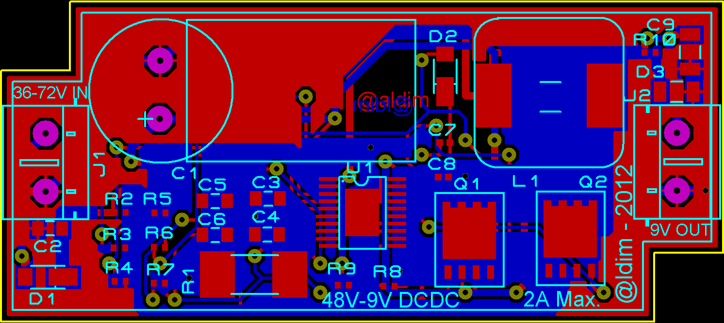
I designed a dc-dc converter with using webench that is 36-72VDC input and 9VDC, 2A output. I realize that circuit at own design PCBequal the webench design.

Problem is the circuit works with 30-36VDC input but if the input voltage higher than 39VDC power dc-dc is shut down and never works again. I see LM5116MH pin14 and pin15 near the short circuit (2,5 Ohm) and the dc-dc is fail.

Please, help me to guide for find my mistake.

regards.

  • Hi;

    I solved this problem.

    First of all you must use two resistor (1K aprox.) with from LM5116MH HO(19) and LO(15) to MOSFET gate.

    Second issue is the only one 10uF output filter capasitor is not enough. You must use electrolitic capasitor (100-470 uf aprox.) and 100nF ceramic capasitor.

    After that the dc-dc (attached shematic) works well.

    Regards.

  • Hey Bulent,

    It's nice to hear that you have resolved the issue. I'm curious as to why you needed to add two 1k gate resistors?  Would you be so kind to share your  PDF of  your layout or a picture of your board and the actual BOM used?  Again, great job and thank you for your support using TI's WEBENCH Designer Tool.

    Regards,
    Howard Chen

    WEBENCH Applications Engineer

  • Hi Chen,

    I needed 1k resistors because, if LM5116 HO and LO port connected to the Mosfet s gate directly and the input voltage is more than 39VDC the LM5116 is burn. The ic is completely damage and will not be use again. I think, Webench program has some mistake for this point.

    Regards,

  • Hello Bulent,

    Thank you for the schematics. My interest is to see the layout because that is the critical aspect of the design whether the application circuit performances well or marginal.

    You mentioned the IC was over heating and it stopped functioning. My questions to you are: Was the IC properly soldered down to the PC board and including its exposed pad?  Was your PCB designed with sufficient amount of copper to extract the heat from the IC?   Also, I have looked over your WEBENCH design and it suggests using 2 X 10uF for output capacitance.  Did you use the exact BOM as suggested by WEBENCH?  if not, the performance of the design will be greatly compromised. 

    Regards,

    Howard

  • Hi Howard,

    The PCB layout is attached. I use exact BOM as WEBENCH and i added two ressistors at MOSFET gates and some outpu capasitors with rework. THe ic is properly soldered with exposed pad and is not over heat but, MOSFETs are over heat and i use a cooling element. Unfurtunately, the cooler is not enough. My PCB layout design is not good for this reason. The MOSFETs cooler pads are not enough. This PCB is only protype and i will re design again.

    Thank you, regards.

  • Hello Bulent,

    Thank you for the sharing the PCB layout. You have mentioned that you are looking to redo your layout, attached is my suggestion for positioning the critical components: such as the FETs, Inductor, Rsense and Cin and Cout. We want to make sure the switch node has sufficient amount of thermal vias and copper areas at top and bottom to cool the FETs. And lastly, don’t rout any traces across the switch node or critical traces adjacent to it.  

    For the MOSFET overheating issue,  it’s due to the added resistance to the gate.  Here is an equation (Switching Power Loss = Vin * Iout * 0.5 (Trise+Tfall) * Freq) approximating the switching power loss. Using WEBENCH calculated power loss for  M1 is 0.42 and the breakdown of the switching & conduction power losses are respectively  0.41 & 0.01 Watt.   The selected FET theta JA is 62 deg. C/watt and it equates to 56.4 deg. C junction temp with ambient temp of 30 deg C.  If I calculate for Trise/Tfall and it's about 10nS.   Since you have added a 1k resistance to the gate, the rise and fall time will be much slower and I will assume the Tf/Tf is 5x slower ( You can scope this).so then Tr/tf are about 50nS   Now, the switching power loss is almost 5 time more and the junction temp of the FET is close to 163 deg C. This is the reason why your FETs are overheating. 

    I would suggest the removal of the added gate resistors and use a RC snubber circuit to help minimize SW node voltage spikes.

    Here is the link for Snubber Circuit Design: http://www.ti.com/ww/en/analog/power_management/snubber_circuit_design.html

    Below is the suggested positions of the key components for you design.

    Regards,
    Howard

  • Hi Howard,

    Thank you for your suggestions. I will try snubber circuit and PCB layout suggestions at my new prototype PCB design.

    I will share results.

    Regards.


  • Hallo Bulent

    Have any verified circuit for LM5116 which can regulate 60 to 120 Volt input voltage to fixed 25 V output Voltage. ( aprx.10 Amp output)

    Here in forum I have read that the WEBENCH has some failures in some designs

    Thanks in advance

    Selim

  • Hello Howard

    I ask a favour of  you ,so, I intend to use " LM5116"  as a charge controller for a wind turbine , it is thought of a regulator of 40 to 100 Volt input Voltage to 28 Volt output with 60 Amps. Would  this IC fulfill  this job or not ? If yes ,under which conditions.If it is inadequate I save me all the job with LM5116  and perhaps you recomment another IC and  circuit .Thank you very  much in advance for your recommendations

    Selim Dumlu

  • Hello Selim,

    For your requirement, the LM5116 won't work.  The only options are to use a half-bridge  or full-bridge converters to support  your >1KW converter..

    I don't know too much about these high power supplies, but maybe someone on this forum can help.

    BTW, WEBENCH does good job creating functional designs and this is validated by Mr. Bulent Kilic's fully working design. 

  • Hello Howard

    Thank you for your guidance,but I already started to build a circuit  I will see how much Amps I can manage with LM5116.Here I will disclose my results.

    Googbye

    Selim