This thread has been locked.

If you have a related question, please click the "Ask a related question" button in the top right corner. The newly created question will be automatically linked to this question.

LM25117 Compensation Network Values

Other Parts Discussed in Thread: LM5117

Good Morning.

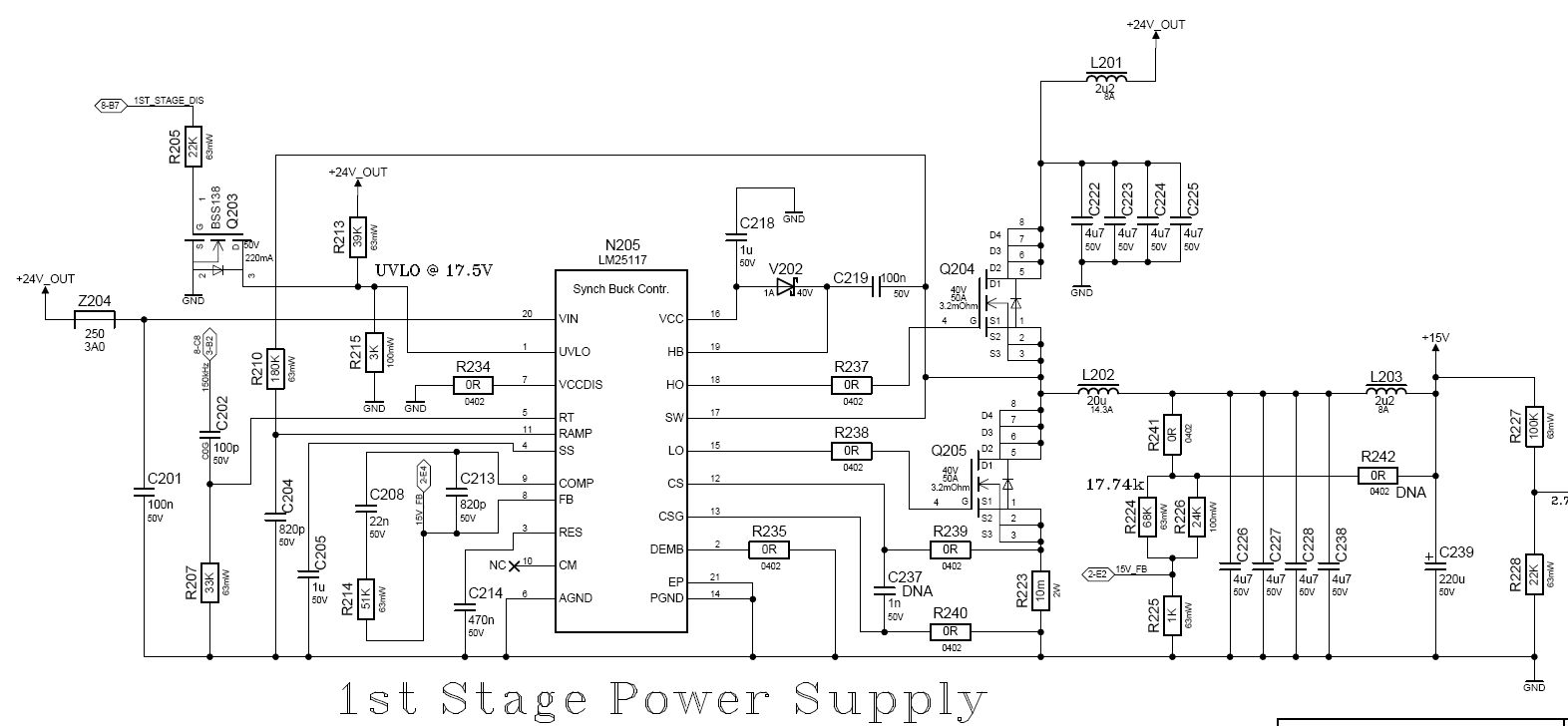
I took over a design from an employee who quit and need help calculating component values for C208, R214 and C213 (see attached file of schematic).

The buck is making 15V output at 5A.

The input is 24 volts but can range from 18V to 30V.

Can somebody please provide me with the equations that I need to use and how to derive the proper values if I were to use R242 for the feedback.

Thanks;

Leo

  • Hi Leo

    Because of the existence of post LC filter, your cross over frequency should be low enough not to oscillate at the LC resonance frequency.

    If you use R241 feedback network, cross over frequency should be below 1 kHz. In this case, R214 can be 220 ohm, C208 is 270nF and C213 is not required.

    If you use R242 feedback network, the same low cross over frequency is required due to the resonance of post LC filter.  R214 can be 2670 ohm, C208 is 270nF and C213 can be about 100pF.

    Some additional comments are;

    Using R241 feedback network is not a traditional way to feedback the output voltage.

    If the output voltage is relatively high like as 15V, it is recommended that a soft-saturating inductor such as a powder core device is used.

    If there isn’t any bad effect on your application, please try to increase C214 up to 10uF.


    Components selection is not optimized for any performance, is just a good starting point.

    Some simple equations about the loop compensation design are on the page 25~26 of LM5117 datasheets for your reference.

    Thanks

    Eric

  • Eric,

    Thank you very much for the response.

    What is the estimated Gain and Phase Margin with the values that you suggest using R242?

    We would like to have 60 degrees phase margin and a minimum of 20db Gain margin.

    Also if possible please provide simulations or mathematics as to how you arrived at those values.

    Thanks;

    Leo

  • Hi Leo

    Phase margin is over 60deg. Gain margin depends on ESR of output capacitor and DCR of 2.2uH inductor. The bigger total resistance will result the lager gain margin.

    I'm sorry that I cannot provide simulations. You can generate your own simulation result using WEBENCH.(See the top right side of http://www.ti.com/product/lm5117  to find LM5117 WEBENCH link)

    Thanks

    Eric

  • Eric,

    So you can not provide the simulation but can you at least still provide some sort of a information as to how you arrived at the values below: Also web bench will not let you simulate this kind of a filter.

    "If you use R242 feedback network, the same low cross over frequency is required due to the resonance of post LC filter.  R214 can be 2670 ohm, C208 is 270nF and C213 can be about 100pF."

    Also:

    L202 --> DCR = 6mOhm

    L203 --> DCR = 10mOhm

    C226, C227, C228, C238 --> X7R Dielectric --> Very Low ESR

    C239 --> ESR = 300mOhm

    Did you use equations or some other tool to come up with these values?

    Thanks;

    Leo

  • It would take extensive time to generate equations for calculating these values.

    This discussion is being handled offline moving forward.