This thread has been locked.

If you have a related question, please click the "Ask a related question" button in the top right corner. The newly created question will be automatically linked to this question.

TPS62130 output change with temperature.

Other Parts Discussed in Thread: TPS62130

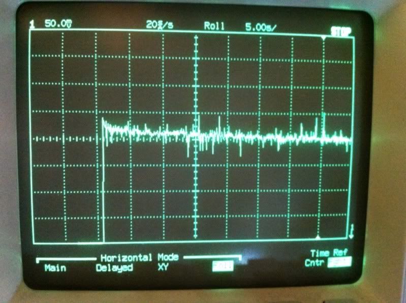
I am seeing Vout start high and then drift down over a 10 second period when driving 3A to the load.  (LED).

If I hit the converter with freeze spray I see the output come down even farther.  If I probe the fb node it appears to be steady around 0.8V during these periods.

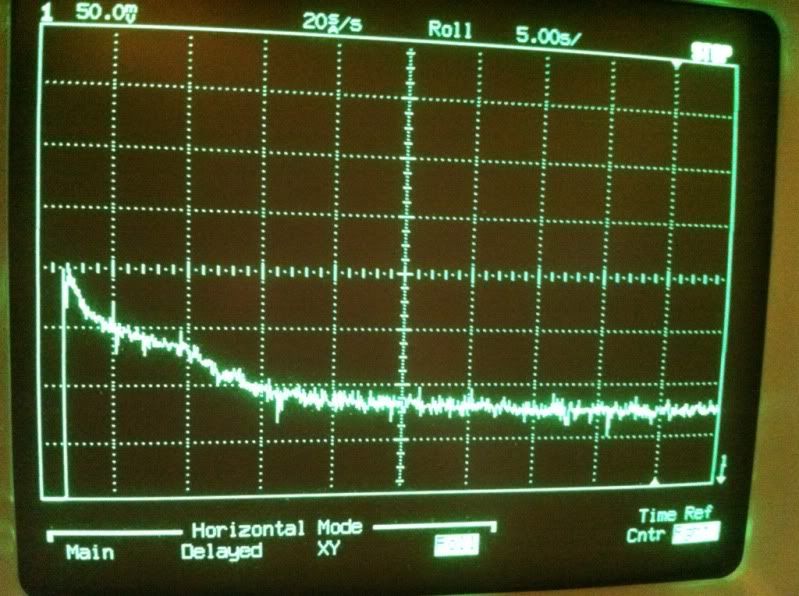
DC offset approximately 3.2V.  (Vf of a Cree XM-L mounted on a large heat sink).  Also, I've tied fsw to Vout.  So, it may start out at 2.5MHz and then switch to 1.25MHz as soon as Vout rises.  Don't know if that is an issue or not.  WIsh I could tie it to Vin, but, Vin could be as high as 9V in this case exceeding fsw voltage specification.

WY

  • You are correct that FSW needs to be tied to vout, not Vin.

    I'm not sure what the waveform is of.  Is it the output voltage of the IC (voltage at VOS pin)?  Since the FB voltage is 0.8V, then the IC is doing its job and regulating.  It's likely just that the forward voltage of the LED starts higher and gets lower as it heats up.  Diode's forward voltages decrease with increasing temperature.

  • Yes, the waveform is Vout.  I have characterized this LED and have many many scope traces at 3A.  I've been troubleshooting the other converter IC issue for over 2 mo's now and know what the Vf drop is and the resulting scope trace should be.  Since the LED is mounted to a large heat sink the rise on the LED over this 50 second period is  relatively small.  Yes, possibly some of this is the VF, but, you see it levels off and is basically flat.  If the LED really was heating up it would continue to rise over this 50 second period.    Besides.  The VF is a negative temp coefficient.  If LED heats up, VF goes down and with a constant voltage applied current goes up.

    The start of this run the LED current was 3.5A and as Vout decayed down LED current leveled off to just tad over 3A.

    The first couple of seconds starting high and decaying is typical of this configuration since I am injecting a PWM signal into the fb node to control the output voltage.  The time constant of the PWM filter network is around 16mS or so and I don't think can account for a 10 second decay.

    As i mentioned in the first post if I hit the converter with freeze spray Vout drops some 50mV.  When I was probling the fb pin and hit the converter with freeze spray I didn't see any change.  Maybe, the scale of 50mV/div was not low enough to see fb change.  (assuming the internal reference changed).

    Is there are graph of the internal reference voltage vs temperature?  I don't think it is in the datasheet.

    If this is the "normal" we can work around it.  Currently the servo current routine is turned off so we can monitor the drift of the converter and see if it burps or hiccups that would cause any flashing or flickering as that was the issue with the ST IC.  I believe I have traced that issue to noise on the internal reference.  I am hoping we don't have the same issues with the TPS62130.

    WY

  • The TPS62130 is wired in voltage control mode.  If the LED current went up or down (load change) Vout should remain constant more or less.

  • The requirement is to put out steady 3A to the LED for 45 seconds.  This is inside a small flashlight and the code will only run 3A for this period to prevent overheating of the light.  

    Any flickering is unacceptable.  Vout needs to be rock solid and stable during the whole 45 seconds.

    There is another issue or requirement.  At low output currents (less than 10mA) any small change in output is very noticeable.  This shows up as flicker if the period is long enough (10mS and longer).  For low output levels the light can not startup brighter than the desired value as this "flashes" the light and destroys any night vision.  We can accomodate some in the fw like delay turning on the light from the off state before enable the LED, but, if this duration is visible by the end customer it is not acceptable.  Thus, delay to turn on can only be up to a couple hundred milliseconds.  Any longer the customer will notice the delay.

  • Hmm, so you are driving the LED with a constant voltage and not a constant current?  Theoretically, this would not be the ideal way to do it.

    It also sounds like it would be a good idea to test the circuit piece by piece--first just driving the LED without a PWM signal applied, then applying the PWM signal, then applying freeze spray, etc.  Debug it piece by piece.

    You might also try ordering the EVM and testing your LED on that.  If you do want to stick with constant voltage regulation, there would be less mods needed to that PCB.

    If the FB pin is always at 0.8V, then the IC is regulating.  If the output voltage is wrong with the FB pin at 0.8V, then there are IR drops somewhere that cause the difference in voltages.

    I do not have data on the drift of the internal reference over temperature but it will always be within a +/- 1.8% range to meet the voltage accuracy spec of the device.

  • The LED is controlled by the microprocessor under normal circumstances.  The regulator is configured as a voltage regulator with PWM control from the uP.  Feedback is from a sense resistor in series with the LED.  The light has 6 programmed levels from 10mA to 3A.  Since the current to the LED is not fixed some form of control is required.  

    Varying the TR pin to change the fb is potentially another method with this IC and I will be using that method in a simplier design with the TPS63130, but, in the uP configuration each light is calibrated to match the uP with the LED attached since the Vf varies from unit to unit or if the LED is changed out under warranty, repair or if the customer requests a different tint variation.

    This is all moot if they all exhibit this behavior.  I am not too concerned since the uP can servo out most of this.  The question is whether it can reign in 3.5a back to 3A fast enough without the end user noticing it.  If the initial deviation is too much it may be come hard to servo it back to the correct output.

    We are testing it open loop just to understand what difficulties, issues or what we need to deal with when we close the loop.

    Here is the EVM with the same LED hookup up to it.  At 3.3V the LED is drawing around 1.8A.  The amplitude and the amount of decay might be larger if it the load was 3A.