This thread has been locked.

If you have a related question, please click the "Ask a related question" button in the top right corner. The newly created question will be automatically linked to this question.

TPS61500 - Problem with LED current : 20mA instead of 400mA

Other Parts Discussed in Thread: TPS61500

Hi all,

I am totally new to this forum and I hope I will be able to find an answer to my problem.

I need a LED driver to drive three LEDs in series at 1.2A (will be around 11V). We found that the TPS61500 module will do a perfect job for that. We ordered a few of these and tried as a test to implement a simple circuit to drive these three LEDs at around 400mA with no dimming at first (400mA as we were not having smaller Rsense resistor at this time, but sufficient as a first test).

However we could only get around 20mA using a 0.47 Ohm sense resistor! We should get  around 400mA according to the datasheet while using 0.47Ohm as Rsense!

The circuit used is the following:

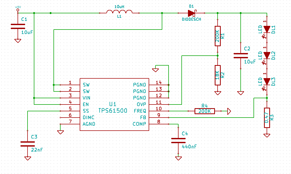
Does anyone has an idea of what we are doing wrong here? We tried twice the same circuit just in case it was a defect of the TPS61500 we were using but we got twice the same result..

Thank you very much for your help,

Bests,

Guillaume

  • Hi all,

    I must add that I am so far connecting all the ground types together (AGND and PGND). Do you think this could have the effect of reducing the ouput current to 20mA instead of 400mA ?

    Thanks again for your help,

    Guillaume

  • Hello Guillaume,

    Which input voltage are you using?

    What voltage do you have on the output of the converter? Is it possible that the part is in overvoltage?

    Is it possible that the inductor is going into saturation?

    Normally your setup should work. It is best to have all GND potentials at the same level, but this level should be a solid GND plane if possible. For DC/DC converters the layout is always important.

    Best regards,
    Brigitte

  • Hello Brigitte,

    Thank you very much for your reply!

    The input voltage used was between 5V and 6V (the voltage generator can give up to 3A so I was far below its limits). I don't think I was in OVP mode as the voltage at the OVP pin where of only 0.6V when we measured and the OVP starts at 1.229V if I am correct. Regarding the inductor I suppose I am not in saturation since it supposed to be able to handle 5A and I am using a 10uH inductor and the frequency is around 500kHz.

    One thing I am wondering though is that on the box the TPS61500 were sent to us is written "Please bake prior to reflow soldering". As I could not find any information on TI's website or in the datasheet about that I did not bake the chips. Do you think this could be the problem? If yes do you know what I should do (never bake a component before ;) ).

    I am trying a new test today with my last chip. I designed something very closed to the evaluation board (regarding the ground planes and general design). I hope this will work, but so far after three tries I always get a problem: the current is 20mA or less instead of 400mA. Kind of disapointing!

    Thanks a lot for your help,

    Best regards,

    Guillaume

  • Hello Guillaume,

    I expect that you got the parts in a moisture barrier bag and that bake before reflow was given if the parts saw moisture during their history or the bag is open for some time.

    Bake means that you put the part for several hours at 125°C before they are soldered.

    I do not expect that this is the root cause for your issue.

    From the schematic everything looks ok, but I would recommend to order the EVM because layout is for switching converters very important and the layout of the EVM is tested.

    Best regards,
    Brigitte

  • Hello again Brigitte,

    and thanks again for your help.

    So I tried with a design similar to the eval board you are selling. And I still get the same problem. I checked the voltage at the FB pin and it is only 0.2mV! So there should be a problem with the internal reference voltage.

    If I connect the EN pin to Vin, should I do something at the DIMC pin? can I let it in the air? Should I put 1.229V as for some applications I saw for Analog dimming? (Application Report SLVA326–April 2009).

    I really don't understand the problem. This driver looks perfect for our product we are designing but for some reasons something is going wrong. I ordered the Eval Board to check if this will really work as expected and additional TPS61500 chips from another supplier, we'll see!

    Bests,

    Guillaume

  • Hello Again,

    The last was unsuccessful. I got the same results: less than 20mA instead of 400mA.

    I think the thermal pad is not properly connected to Aground, as specified in the datasheet. Anyone knows if this could be the problem (if the thermal pad is not connected to AGROUND)?

    Thanks a lot for your help,

    Guillaume

  • Hello Guillaume,

    When you measure 20mA through the LEDs and there is just 0.2mA on the feedback pin, I wonder if this pin is shorted to GND. Normally with 20mA through the LEDs, you should measure around 10mA on the feedback pin because of the voltage drop on the external resistor.

    Please check the softstart pin as well. Is the IC switching?

    Best regards,
    Brigitte

  • Hello Brigitte,

    We received yesterday the eval board and a new batch of TPS61500 module from a different supplier. The eval board works perfectly and surprise, with the exact same design as previously, the module worked fine as well. So I guess the first batch we received was defective.

    Therefore problem solved!This was not a design problem but a chip problem.

    Thanks a lot for your help Brigitte,

    Bests,

    Guillaume

  • Hello Guillaume,

    Many thanks for the update.

    I hope you meant: This was not a chip problem but a design problem?

    Best regards,
    Brigitte

  • Hello Brigitte,

    Sadly I did mean a problem with the chip, not the design, as I used the same design with two different chips from two different supplier, one was working, the other not (in fact 4 from the same supplier were not working). There is still a possibility that I misconnected something tfour times of course.

    But many thanks for your help, I really apreciate it, it helped a lot discovering what was the problem!

    Bests,

    Guillaume