This thread has been locked.

If you have a related question, please click the "Ask a related question" button in the top right corner. The newly created question will be automatically linked to this question.

UCC28070 restarting

Other Parts Discussed in Thread: UCC28070

Dear All,

I am trying to build PFC with UCC28070, I have only first version of PCB and I already know that my layout isnt good enough and need to be rerouted. But even with this i should be capable to findout where is problem with my design. According to my scope measurement it seems that IC is periodicly reseting it self but for now i dont know why?
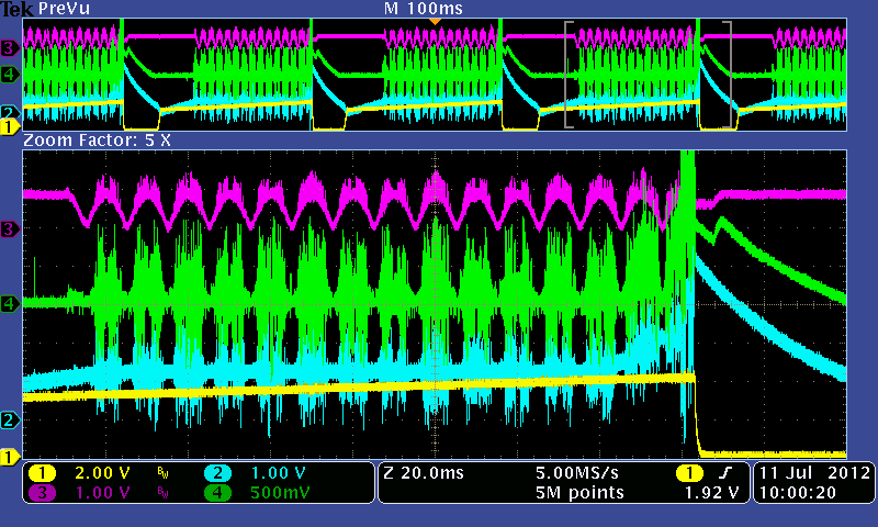
  

Channel 1 is SS pin

Channel 2 is VAO pin

Channel 3 is VINAC pin

Channel 4 is IMO pin

This design was created according to you xls file for correct selection of component values.

Parameters of PFC 1500 W, Uout 400 V, external synchronization at 200 kHz (generated frequency is 400 kHz)

Test conditions: Uin 85 VAC, Uout 400 V, Rload=20 kohm (with smaller resistance output voltage starts to fall down)

During normal conditions is PF over 0,9, but it is highly lowered during reset condition.

I am sorry for so much interference in this picture, but my probes are with large signal loops and some signals are deformed because of layout. (tested by probe with small signal loop)

According to

Thanks in advance for any suggestions.

  • According to datasheet, there are only 3 conditions for restart:

    1/ over heat of IC - checked by thermocamera and it seems to be ok

    2/ undervoltage on VSENSE - checked by probe with small loop and it seems to be ok

    3/ undervoltage of UCC28070 - checked by probe with small loop and it seems to be ok

    Can anybody send me or post correct form of signal SS or describe what is happening in my design?

    I have same troubles with reseting (pin SS pulled-down to gnd) during power on and it takes about 20 second to reach 400 V output level.

  • I would relook at the Vsense input because teh botht he VAO and IMO are increasing dramatically just prior to shutdown.  This would indicate that the Vsense voltage is dropping.

    If you don't find the problem attach a schematic with component values and i will take a look at it.

    John

  • Thank you for your help, I will test it probably tomorrow.

    I have same problem during power on phase, when output voltage is lower than 400 V. It will take about 20 second to reach 400 V (without any load) because of reseting.

  • Dear John,

    Thank you for your help. I relook Vsense voltage and find out that I measure over-voltage condition about 3,4 V (460 V) for 40 us after reset. So I focused myself on grouding near voltage devider and found mistake in my design. I had connected devider to power ground instead of signal ground.

    Now I have trouble with voltage and/or current loop. Output voltage isn't stable but it is changing from 380 V to 460 V, but I hope that this I will fix on my own.