Hi,
A while back I designed a system which uses multiple TLC59108 and TLC59116 to play back patterns etc on many LED's. The customer is very happy with performance etc, but now would like a global dimming feature implemented to reduce brightness. I thought this should be quite straight forward, since as the dimming switch is pressed I could simply re-initialise the drivers but use a new GRPPWM value.
The TLC59108 are all off one I2C channel of the microcontroller, the TLC59116 off the other. I made all the modifications to both channels. The TLC59108 are dimming as expected, but for the life of me I can't seem to get the TLC59116 to respond. It is like they are ignoring the GRPPWM value.
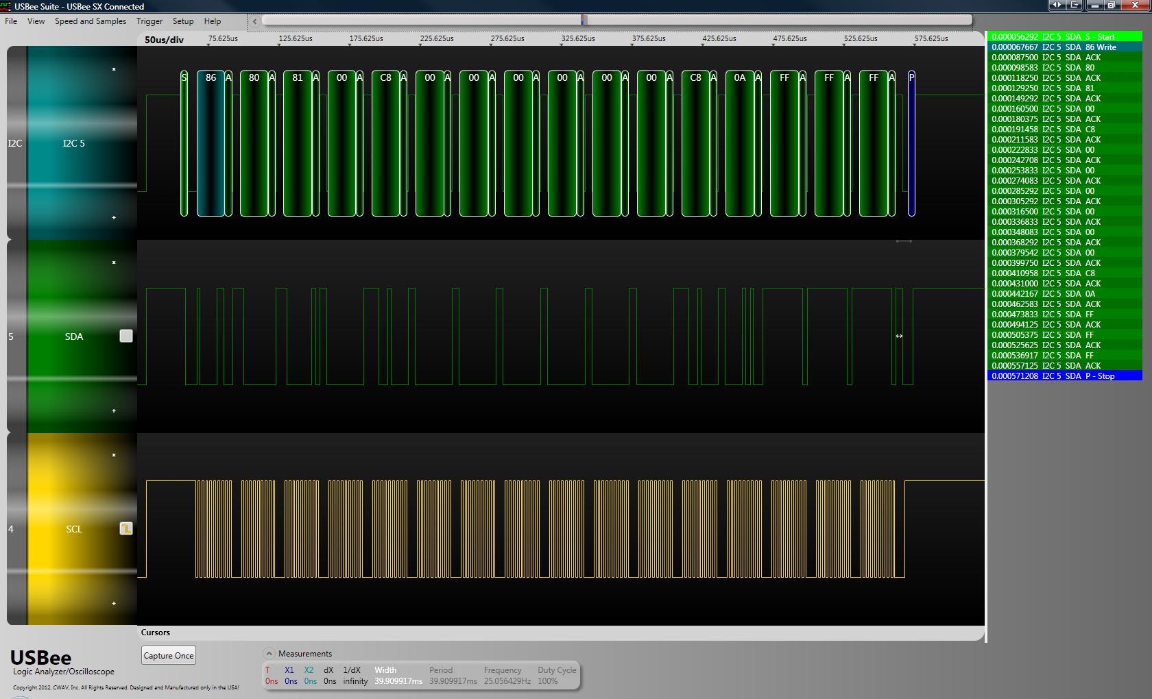
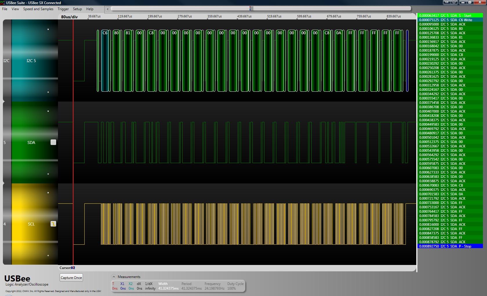
Below is the data which is being sent out as part of the initialisation:
-----------------------------------------------------------------------------------------------------
#define TLC59116_INIT_DATA_LENGTH 25
// Data payload to initialise TLC59116.
unsigned char TLC59116_INIT_DATA[TLC59116_INIT_DATA_LENGTH] = {
0b10000000, // Control Register. // TLC59116 Internal Register:
0b10000001, // Mode 1. // [0x00]
0b00000000, // Mode 2. // [0x01]
0xFF, // Brightness control LED0. // [0x02]
0x00, // Brightness control LED1. // [0x03]
0x00, // Brightness control LED2. // [0x04]
0x00, // Brightness control LED3. // [0x05]
0x00, // Brightness control LED4. // [0x06]
0x00, // Brightness control LED5. // [0x07]
0x00, // Brightness control LED6. // [0x08]
0x00, // Brightness control LED7. // [0x09]
0x00, // Brightness control LED8. // [0x0A]
0x00, // Brightness control LED9. // [0x0B]
0x00, // Brightness control LED10. // [0x0C]
0x00, // Brightness control LED11. // [0x0D]
0x00, // Brightness control LED12. // [0x0E]
0xFF, // Brightness control LED13. // [0x0F]
0x00, // Brightness control LED14. // [0x10]
0xFF, // Brightness control LED15. // [0x11]
10,//0b11111111, // Group Duty Cycle Control Register (GRPPWM). // [0x12]
0b11111111, // Group Frequency Register (GRPFREQ). // [0x13]
0b11111111, // LED Driver Output State Register 0 (LEDOUT0). // [0x14]
0b11111111, // LED Driver Output State Register 1 (LEDOUT1). // [0x15]
0b11111111, // LED Driver Output State Register 2 (LEDOUT2). // [0x16]
0b11111111 // LED Driver Output State Register 3 (LEDOUT3). // [0x17]
};
-----------------------------------------------------------------------------------------------------
As part of my fault-finding, I have stripped the code back and have removed all but one TLC59116 device from my board and it is configured as:
A0 = 0
A1 = 0
A2 = 1
A3 = 0
So a write will be: 0b11001000 = 0xC8
And a read will be: 0b11001001 = 0xC9
The control register should be set to auto-inrement all registers starting from register 0b0000.
Mode1 register has 100 for the auto-increment, not sure if this matters since it is a read-only register? OSC = ON, ignore subaddr, listen to all-call.
Mode2 register has error status enabled, Group Control = dimming, outputs change on stop.
My test board has all 16 outputs connected, but the final product has only 14 so for the purposes of testing I have LED0, 13, 15, ON at full brightness.
I can see all the above data going out, and can even read back all registers and see the GRPPWM register saying it has the value 10 stored in it... If I change the DMBLNK to '1', the outputs will blink (when GRPFREQ is set lower) which proves the LEDOUT options are set correctly, ie responds to dimming/blinking. At the moment all the code is doing is sending the initialisation, and then either some test data, or doing a read back depending on my testing.
I did come across another thread talking about issues with the GRPPWM which had no answer:
http://e2e.ti.com/support/power_management/led_driverslcd_bias/f/192/t/153172.aspx
Are there any differences (other than more outputs) between the 8-channel TLC59108 and 16-channel TLC59116, I did not come across anything in the datasheet?
Can anyone provide any insight into what could be going wrong? If needed I can provide a I2C trace of the data going out/in.
Thanks,
Bernard.