This thread has been locked.

If you have a related question, please click the "Ask a related question" button in the top right corner. The newly created question will be automatically linked to this question.

LP3971 start up problem

Other Parts Discussed in Thread: LP3971

I asked this question through TI's technical support and the reply was to post here for information.

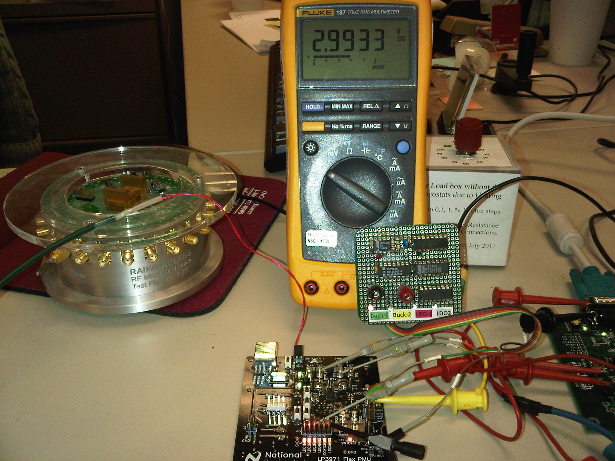
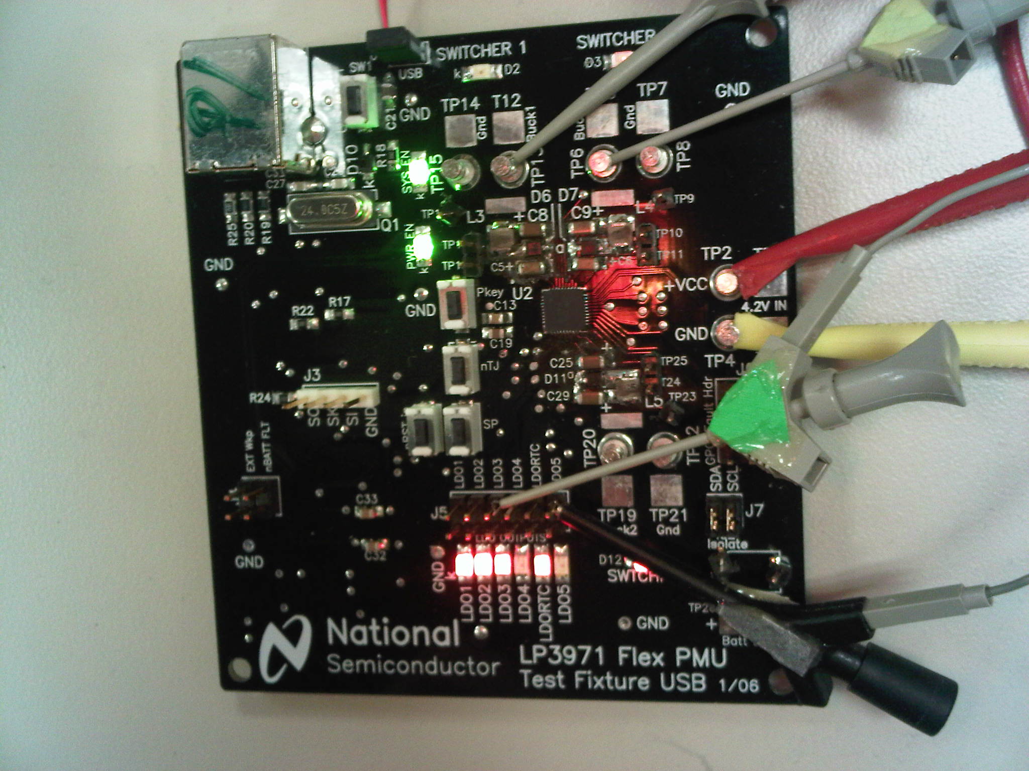
The LP3971 Power Management Unit does not always start. SYS_EN is high but Buck 2 and Buck 3 are not on. The application note at the end of the data sheet has a cold start power sequence. In this sequence there is a delay between SYS_EN and PWR_EN. In the documentation for the evaluation board, SYS_EN and PWR_EN are tied together. How important is the timing shown in the application note? The note only has typical times for most signals, no Max or Min.


What could be causing Buck2 and Buck3 not to start when both SYS_EN and PWR_EN are high?

  • Hi Craig,

    when you say not always start, does it mean the PMU not startup at all, or just Buck2&3? I checked the eval board schematic, SYS_EN and PWR_EN are seperate signal path, but there is an indicating LED for each of them, do you see both LEDs on during startup? can you read the register through I2C/GUI when Buck2/3 are off?

  • I do not have the eval board. I was looking at document SNVU097.pdf (LP3971 Smart Power Reference Design - 8 output) linked under users guides on the LP3971 product page. In the schematic on page 2 SYS_EN and PWR_EN are tied together.

    When I say that the Buck 2 and 3 do not start, the regulators that are enabled by SYS_EN (Buck2, Buck3) do not power ON. I am not using the linear regulators that are enabled by SYS_EN so I have not checked them. The regulators that are enabled by PWR_EN do turn on (Buck1, LDO4, LDO5).

    The Application note at the end of the data sheet only gives typical delays no max or min. How critical is the timing?

  • Hi

    I checked the our eval board today, and both buck2 &3 startup without any problem regardless of SYS_EN and PWR_EN asserts sequence. However, the datasheet does state the LDO1 should be power first for internal logic I/O, bandgap etc. So I suggest you should have some delay between SYS_EN and PWR_EN, 125mS will be a start point. which silicon version are you using?


  • The problem is intermittent. Buck 2 and 3 sometimes start and somtimes do not. They either both start or neither starts, it has not happened where one starts but not the other. Probing the SYS_EN and PWR_EN with a scope probe is often (but not always) enough to get things started.

    I am not sure of the version of silicon, the parts were bought from Digikey within the last 4 months. However we have been experiencing this problem on and off for the last 2+ years.

    I think the powering of LDO1 reference in the data sheet is for the example processor. The OSC13M and PLL etc are functions of the microprocessor.


  • Also, if the problem is not related to the timing on SYS_EN and PWR_EN, what could be preventing Buck2 and Buck3 from turning on?

  • HI Craig,

    Have you resolved or located the issue with SYS_EN not enabling Bucks2 & 3?  We have not experience this reporting before.  One thing you mentioned of obtaining the devices from DigitKey, wondered which flavor you had. For example, the LP3971SQ-2G16, LP3971SQ-7848, and LP3971SQ-8858 part types all have the Buck2 enabled by PWR_EN and Buck3 remains enable by SYS_EN!   So that can not be they case if both bucks were not enabled by the two enable pins.  Are the Vin levels and the Ven levels compliant to the DS?  Are all power pins tied to the same rails. That is there are not different voltages powering the various Vin power pins, and that all unused logic pins are tied to Vdd or ground level.  Moreover, unused regulators power pins control pins should not  be floating, tie them to power (or ground for digital inputs as appropriate).   Other than the above the pcb, layout or platform used should be examined.  Is there some snaky leaky paths?  Last;ly try obtain an EVAL board and cross examine between your setup and the EVB. and let us know.

    Regards,

    Kern

  • I got the regulator to start up properly using some RC time constants and some comparators.

    It is interesting that on the schematic for one of the eval boards both SYS_EN and PWR_EN are tied together, but the timing diagram in the data sheet shows that one should be delayed from the other. I could not get an explanation for the difference and whether the delay in the data sheet is realy required.

    I am using a single power supply for the chip.

    I still do not know why when the SYS_EN and PWR_EN were high some outputs were not enabled. In this case, if I glitched (brief pulse low to high) on the enable pins, the regulator would start up.

  • Hi Craig,

    I just got back to the office and wired up the newly arrived LP3971 EVB in my office. (See photos below.)   The default voltages of Buck1 and Buck2 in the PMU are 1.5 V and 1.8V  respectively, the buck1 on-indicator LED is too dim to show up, the DVM indicates the correct voltage.  The regulators whether loaded or not loaded the SYS-EN and PWR-EN tests appear normal, issued no sign of failure in enabling the regulators as reported.    I am perturbed by your phenomenon and especially on some delay was required.   Have you done similar "manual" testing as described below?   Would like to have glimpse of your set up ... a picture would be helpful.      It  bothers me when you conveyed that the phenomenon has been on going for many many moons!  And I like to apologize that you have not gotten the attention you deserve;  understandably this might have an element with the TI merger.


    Picture left atop shows the setup where EVB power by +5V switching supply.      Top right photo is an expanded view of the LP3971 EVB.  Note that the

    PWR_EN =SYS_EN tied togeter, either connected to +5V and cycling the               red wires by J1 jumper are the PWR_EN and SYS_EN wires used to control

    supply, or with the +5V supply on manually connect the enable-pins to GND         assertion of regulators.     Loading Buck1, Buck2 with a 1.5ohms power

    and +5V alternately.  Result:  the bucks always turn on properly.  A mux                  resistor does not show any adverse effects.  The system and powers controls

    contraption monitors 4 regulator outputs and feed them to a DVM.                            appear working normally.


    Please give me addition info and waveforms of the enable pins.  Also the circuit and time/amplitude information of the delay used will be nice. I will continue check it out in the lab to determine if amplitude, slew rate, etc. might be influencing the enabling functions. 

    Regards,

    Kern

  • Kern

    The design was a legacy design. The attempt to implement the start-up delays mentioned in the data sheet were done using R/C time constants. This resulted in the SYS_EN and PWR_EN being switched from an R/C instead of using logic levels.

    On the new board I have placed comparators between SYS_EN and PWR_EN and their R/C's. Giving the SYS_EN and PWR_EN a clean edge transition seams to have solved the problem.

    We have built 65 boards with the comparator circuit and all are working properly.

    Craig


  • Craig,

    Good to learn your boards are working properly after you implemented some delay between the SYY_EN and PWR_EN.   The delay is prescribed by the PXA-27x, in general the enables can be asserted together.  Just like to update you on our lab exercise results.  We dropped Vin down to 2.7V (same for ENs) and in combination with EN edge rate varied from 5 ns/V to 175ms/V,  and did not observed any start-up phenomenon on the bucks and LDOs.    Should you have any questions, issue in the future don't hesitate to contact us.     Thank you.

    Kern