I am working with the UCC2802 Current Mode PWM controllers. I currently have a buck converter design that is based on a previous design that was supplied to me. It is designed to operate at a switching frequency of 11kHz and step 300VDC down to 12.5VDC. I have very good output voltage regulation when the output does not go above a 2.5A load or 30W. The problem is that the converter is designed to have a maximum output of 10A or 125W.
While the converter is operating normally it has a nice 11kHz PWM gate drive. As the load is increases the switching frequency transitions to about half of what it should be and the output voltage begins to drop. What other reason would there be for the controller not to be running at my fixed switching frequency, is it a current limit problem? There also appears to be a problem with the controller when it needs to go above a 50% duty cycle.
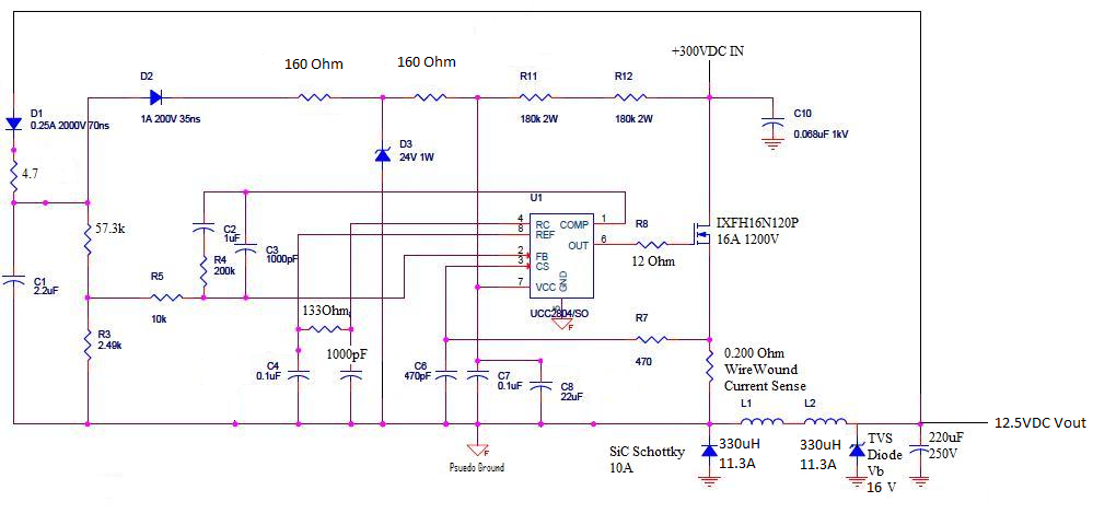
A schematic of a 48V version of the converter that uses a UCC2804 is attached6648.48V Supply Rev3 Schematic.pdf. This is the design I am working off of. I have made neccissary changes for operating within my parameters except for the current sense and comp sections of the circuit. An explanation of why the converters do not run at their set 11kHz frequencies and an explanation of the current sense and over current thresholds section of the datasheet would be very helpful.