This thread has been locked.

If you have a related question, please click the "Ask a related question" button in the top right corner. The newly created question will be automatically linked to this question.

UCC28070 problem

Other Parts Discussed in Thread: UCC28070

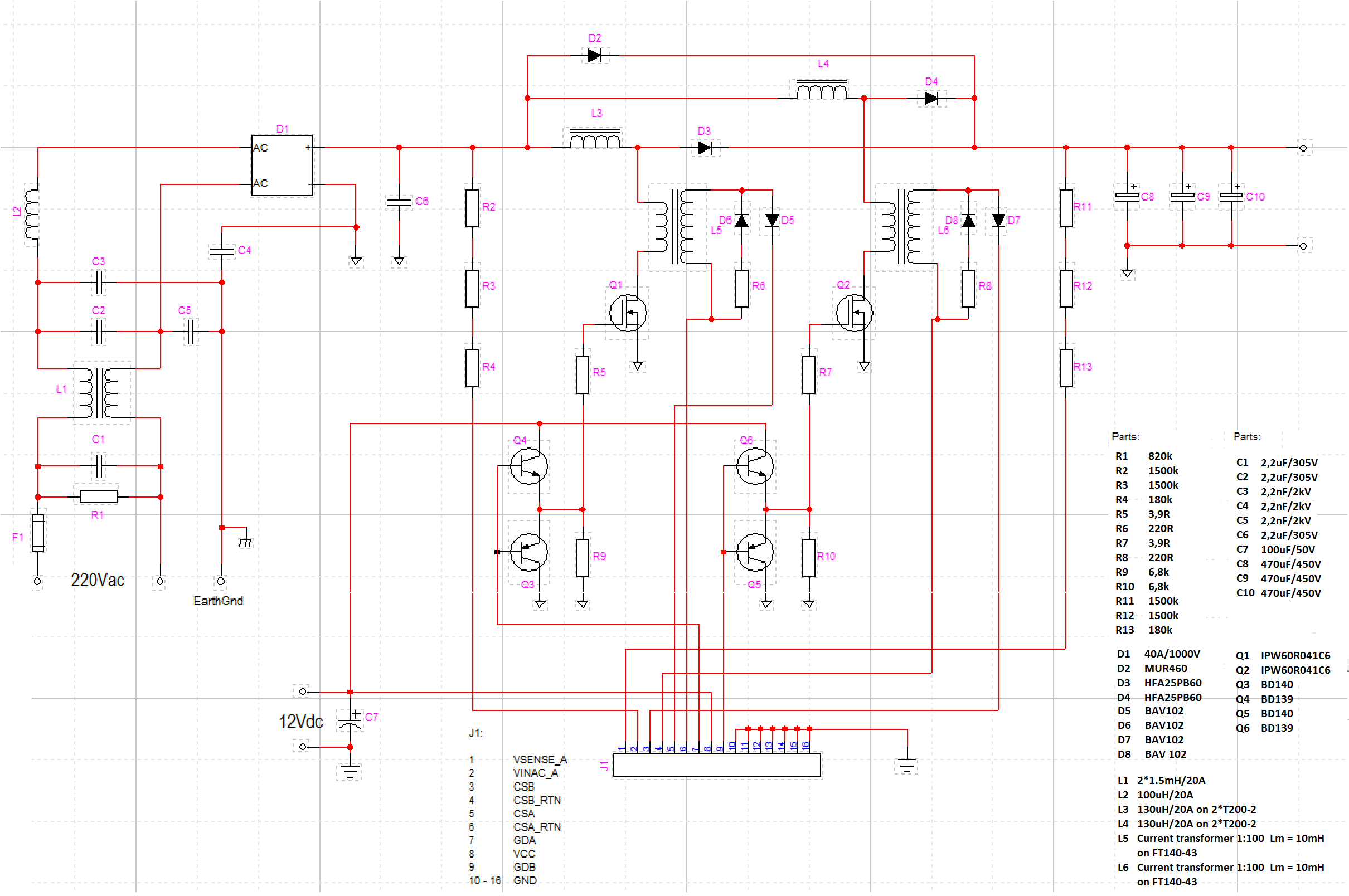
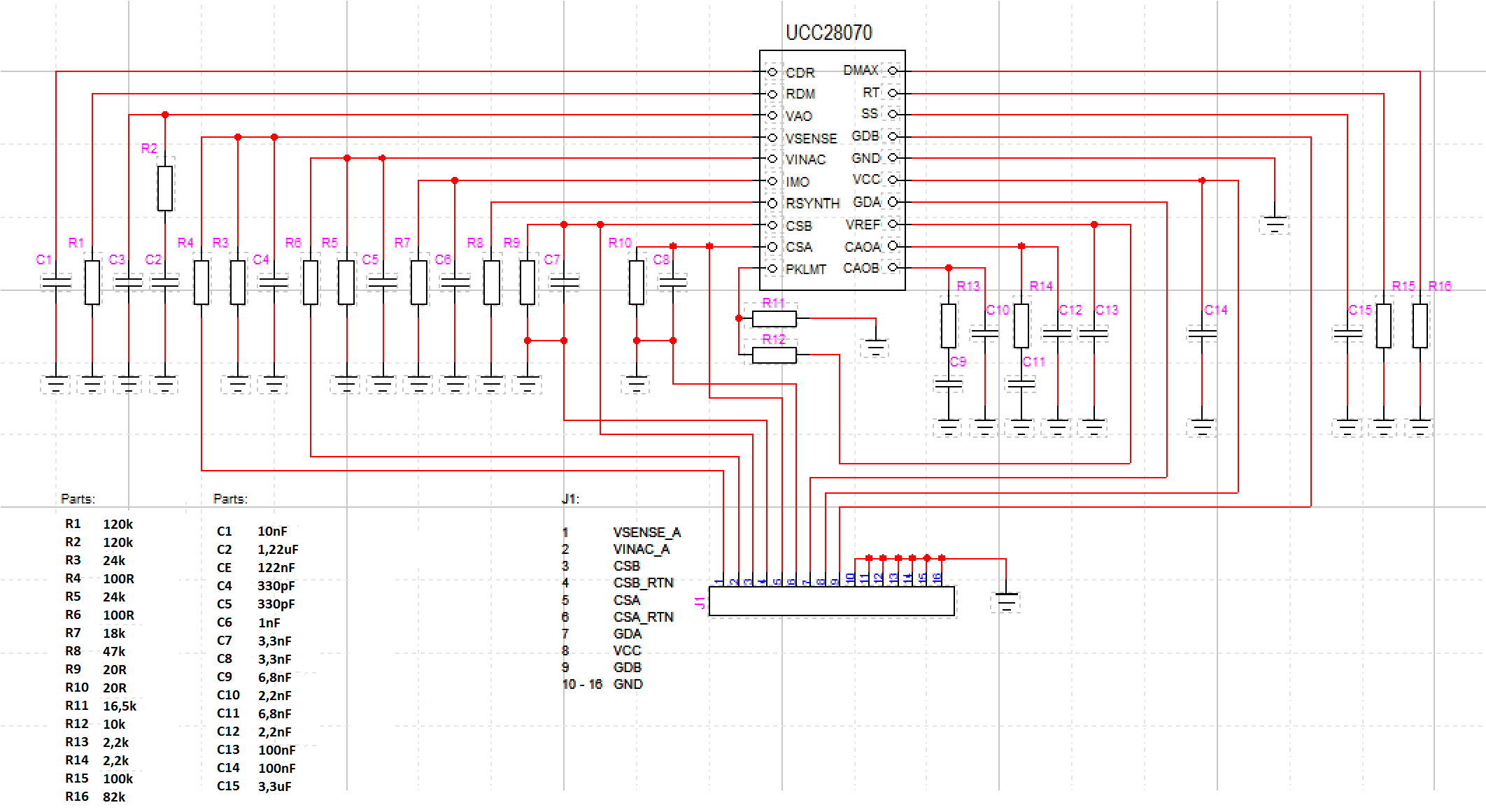
Hi all. We are testing a new design based on the ucc28070 controller, which is very similar to the PR779 1,2 kw PFC and having difficulties. On the first two tests the mosfets on one phase have blown up (very high input currents, large output voltage fluctuations with peaks of over 1000v and also sounds coming from the inductor). Each time the ucc28070 was also affected, as between pins 15 and 17 we measured a small resistance (22ohms aproximately). We were using MCP1407 to drive the mosfets, but now we switched to a 2-transistor buffer because the drivers also blew up.

On the third test we disconnected both mosfets and supplied power only to the ucc. we also supplied Vsense with 1,3V to keep the circuit running.

Without applying any voltage on the CSA and CSB pins, the duty factor was the programmed maximum (90%). When we applied voltage to CSA (0-3V) , the duty factor started to decrease with increased voltage.The decrease started at about 1,4V.

The VINAC pin seemed very sensitive as even a very small voltage (milivolts) caused the duty factor to go maximum and stay there regardless of the voltage being disconnected afterwards. We mounted 4,7nF capacitors on the VSENSE and VINAC pins. The threshold at which the duty factor started to decrease was not 1,4V anymore but 0,8V.

We observed that if we apply voltage to both CSA and CSB the threshold moved back to 1,4V.

The circuit seemed insensitive to VSENSE voltage variations up to 3V , value at which it went into OVP. 

  Another yet more important problem is that any AC voltage applied at VINAC caused the duty factor to go to maximum (shouldn't it vary with applied voltage, going up close to the zero crossings and down on the peaks?).

The values were calculated using ucc28070 excel design spreadsheet. We took a close look at the pcbs and there is no error there. The ucc was soldered with hot air in the minimum amount of time. We have experience with switchmode power supplies and designed the circuit with regard to the PR779 evaluation board layout. The inductors used were wound on 2 T200-2 cores each with a inductance of 130uH. Current transformers were wound on 43 mix ferrite cores at a 1:100 ratio.

Thanks in advance for any suggestions.

Regards

  • When Vsense is 3V, the UCC28070 is in regulation - e.g. at 400V output.

    Do you have leading edge blanking on your current sensors or some sort of damping of the ringing from the inductors?

    Could you provide a schematic?

    Use only 1nF on VINAC. Don't apply caps on your Vsense. If you use caps, the regulation will be slower.

    Try to use the SI8503 instead of the current transformers. And then adjust the signal level on PKLMT (peak limit). The SI8503 gives 2V output at max current - e.g. 20A measureing = 2V out. This signal you can compare to PKLMT (use resistordivider from VREF (6V) to PKLMT) to match max current through MOSFETs/SI8503.

  • Hi, this is the schematic we are using right now.

    Regarding your suggestion to use SI8503 we currently do not have this component and would like to stick with the current transformers for simplicity.

    We do not have leading edge blanking on current inputs as you can see; the damping networks would have been added during testing ... if only it would work without blowing up ... 

    I forgot to mention on the second test we used only 50Vac at input with a small load of only 5kohms. The idea was to ramp up slowly the input voltage after we measured some waveforms on the circuit and made sure everything is ok but no luck.

  • Hello Marius,


    Did you get this problem resolved?  We are looking to use this part too and wondered what the problems are?

  • Hello Adrian,

    Sadly no ... after having spent many long nights, we could not get it to work properly and due to time constraints we abandoned this project to focus on more lucrative ones. As far as we got, it's not blowing up any more expensive mosfets but the input current distortion is horrible and we didn't bother to test at higher power levels. Overall the circuit as a whole is extremely sensitive, not something I would put in production. That is just my opinion and limited experience, maybe others with more knowledge could be able to make it work ok.

    All the best

  • I had full success at 5.7A @ 383VDC output using UCC28070

    I faced many problems, but resolved them ALL after working hard for many hours.

    PFC circuits are so tricky, no matter witch chip you are using