Is it possible to enable and adjust Undervoltage Lockout when you are using TPS54160 as inverting converter? Than you
This thread has been locked.
If you have a related question, please click the "Ask a related question" button in the top right corner. The newly created question will be automatically linked to this question.
Is it possible to enable and adjust Undervoltage Lockout when you are using TPS54160 as inverting converter? Than you
I mean, enabling an UVLO for the input voltage. In the normal buck Converter, The input voltage supplies 2 resistances making a voltage divider to introduce the proper voltage in EN pin. The problem appears when you use the TPS54160 as inverter because the device's ground is now the output voltage. Anyone knows of that is possible?
Hi Jesus,
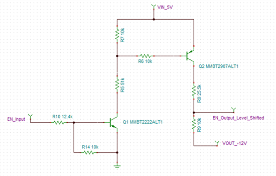
It is possible to use the EN function when configuring a buck in an inverting configuration. It is not as easy as a simple voltage devider though. You will need to level shift your enable signal down to the output voltage via transistors. Below is an image of a level shifting circuit used for an output voltage of -12V.
The main things to consider with this design is that you ensure the EN pin of the TPS54160 is not overvoltaged and that the EN signal is high enough to turn on the IC both when the output is regulated (-12V in this case) and during startup.
At startup, the TPS54160 sees a Vin of 5V with a reference to the system ground (considering Q2 on and resistors R8 & R9 only). The EN pin then follows the same electrical characteristics outlined in the TPS54160 datasheet. Thus for EN to turn on you have 5V*(R9/(R8+R9)) >= EN logic high (1.55V max in the TPS54160).
During regulation, you now have the -12V reference and you want the threshold to be at least -12+1.55=-10.45. Additionally, you need to ensure that the EN pin voltage is NOT greater than -7V (-12V+5V=-7V) to not overvoltage the pin. The equation you get is -12V+(12V+5V)(R9/(R8+R9)) >= -10.45.
Resistor R6 limits the current into Q2, and resistors R5 and R7 create a voltage divider to turn on Q2 when the EN_Input is high enough. Resistors R10 and R14 create another voltage divider to guarantee that Q1 turns on when the EN_Input reaches above the desired voltage. You can define R10 and R14 by using the equation 1.55*(R14/(R14+R10)) = 0.6V where 0.6V is the saturation voltage of the transistor I used.
Regards,
Alex