This thread has been locked.

If you have a related question, please click the "Ask a related question" button in the top right corner. The newly created question will be automatically linked to this question.

TPS61175, unstable operation

Other Parts Discussed in Thread: TPS61175

Hi, I have a question about TPS61175.

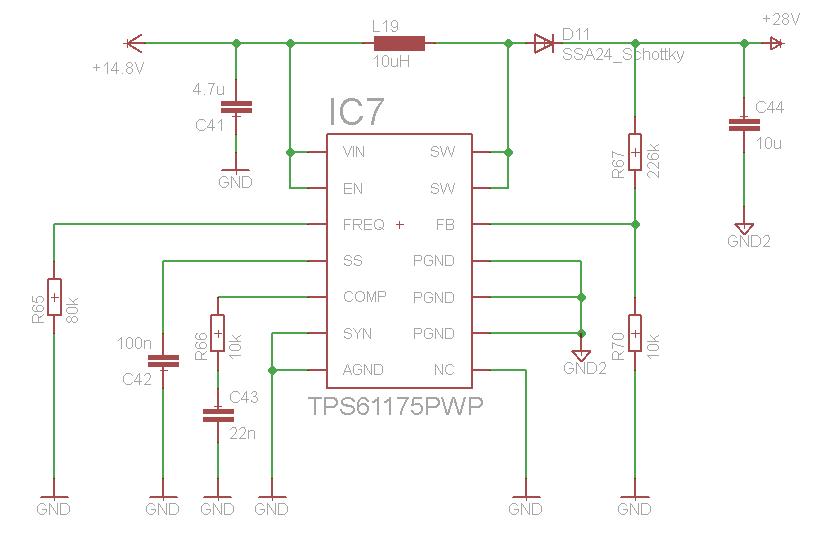
I use this step-up converter in my applycation for making from 15VDC - 28VDC. Layout and elements are the same, as in guidelines in datasheet. 

But it's working in the following way: sometines, when I switch on my application, on the output it is the same voltage as on the input - 15V. But sometimes everything is ok, and I have on the output 28V, what I need. I don't see any logical explanation, every time I switch off and switch on my circuit, it either works as it should work and I have 28V on the output, or it doesn't work at all and I have have the same voltage as the input voltage - 15V.

What could be made wrong in the circuit?

Thank you,

Michael 

  • If the output voltage is the same as the input, then the IC is not enabled.  It is not switching and boosting the input voltage.  Could you verify that your En pin is a logic high?  Can you post your schematic?

    It might also help to look at the various nodes with a scope to debug the circuit.

  • Yes, my En pin is logic high. You can see it from schematic.

    Perhaps, it is because of Cout. Maybe I should insert a discharge resistance, that will discharge Cout after shutdown. But in the datasheet there is nothing about it.

  • Hi Mykhalio,

    Just one question.. Have you connected GND2 and GND ? the random behavior you mentioned above could be due to unconnected grounds.. If you see the figure 18 for layout in datasheet although  PGND and AGND are different ground they are connected to each other.. also as per layout you should have a close & thick + short connection between input ground (of C41) and output ground (c44). If both GND and GND2 are connected then energy across c44 will get discharged through R67 & R70.. If both ground are not connected in your board you can try connecting them at one end & you can see if you still get the same behavior.. This could probably the only reason I can see in above schematics.. rest of things look ok to me

  •  I have connected PGND and AGND, so as in datasheet. But I will try it tomorrow to improve my layout for connecting them as close & thick as possible.

    Thank you very much for the answers!

  • Michael,

    Could you resolve the issue ?  Did you find the exact problem ?

    Thanks,

    Rizwan Hirani

  • Hi Rizwan,

    I found out, that on the ground around the converter there was always 20mV. So I made some extra connections to the ground area in other parts of my board, and since than threre is 0V on the ground around the boost-converter, so as it must be on default. And it works now correct. 

    I haven't understand yet, where was the mistake exactly. But it was for sure something wrong with ground. Perhaps was the ground layout faulty.

    Thank you,

    Michael