This thread has been locked.

If you have a related question, please click the "Ask a related question" button in the top right corner. The newly created question will be automatically linked to this question.

LM3150 unstable issue.

Other Parts Discussed in Thread: LM3150

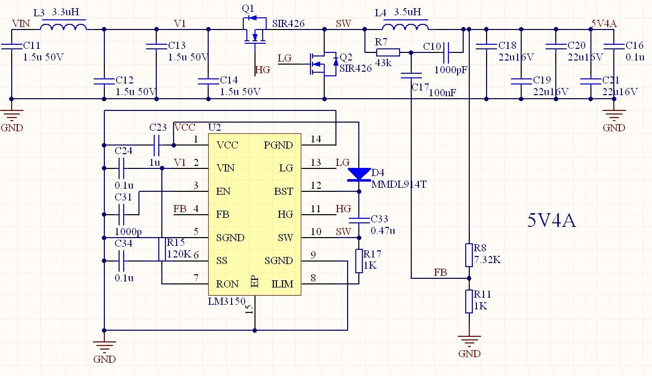
Hi,I am designing a 5V 4A buck converter with LM3150, the input voltage range is 16V to 32V.  The output CAP is 4* 22uF ceramic. Please see the SCH & PCB as attached.

I find the waveform at SW node is unstable,  it seems there is low frequency in the waveform, and the output voltage ripple unstable either. There is even audible noise at full load.

I measured the waveform on FB node and find large voltage spike. I'm not sure if this is the reason lead to the unstable.

I learned the AN1481 and calculated the R7 and C10 of 100K and 3300pF, but i found that if i use smaller value of R7, the circuit works better, but still unstable. Also the output voltage increased with smaller R7.

I thought the layout of power stage is not good. I tried to place a 1.5uF ceramic CAP across a & b ( in the PCB) node on bottom layer, but no effect on the stability of circuit.

Please help to check my issue, and give me some advice. Thank you very much.

Best regards,

Baochao.


  • Hello Baochao,


    just to make sure, can you put a bulk capacitor at the input? something like 100uF electrolytic?

    If the input filter is not well designed there may be some instability problem.

    Please let me know.

    Regards,

    Giuseppe

  • When you lower the value of R7 the ripple on the FB will increase.  This will effectively raise the output voltage.  This can be adjusted after the values for the feed forward have been tweeked.


    I would place a tantalum polymer such as the T520B107M006ATE018 in place of one of your ceramic capacitors as a test.  This will have higher esr which should improve the consistency of the switching frequency.


    Marc


  • Hi Giuseppe,

    Thanks a lot for your suggestion. I tried to place a 1000uF bulk CAP at the input. The circuit is still unstable. Maybe there is other reason.

    Regards,

    Baochao

  • Dear Marc,

    I found the line regulation also goes worse when use lower value of R7.

     I will try to use a tantalum CAP at output. And let you know the result. Thanks.

    Baochao

  • This is an old post, but if you still have the problem. Here is why you have unstable issue: 


    C17 (100nF) is tooo big. Use only 560pF. 


    And BTW, D4 no need for it as there is one inside the IC. And some other design issues: like capacitors values between L3 and Q1 is too low, this will provide unclean Vin as the High frequency of the Q1 and the High impedance of the L3 at that frequency will create high ripple on the input side which is given to Vin and RON , prefer to delete the L3 or add more caps in between.


    Goodluck