This thread has been locked.

If you have a related question, please click the "Ask a related question" button in the top right corner. The newly created question will be automatically linked to this question.

UCC28019 inductor selection

Other Parts Discussed in Thread: UCC28019, UCC28019A, TL431

Hi Team,

For the UCC28019, the datasheet suggests the Vitec 55P9354 inductor (PFC boost, 1.25 mH, 7A, 2.50 inch dia.). I am trying to find one with matching criteria but smaller in size. I looked at Vitec 59P8970 (http://www.viteccorp.com/data/DataSheetTP/af4256.pdf) which is 1.2mH, 10A but only 0.231 in x 0.242 in x 0.228 in. Can anyone see if this works or know if there is another part that work.


Regards,

Brian Wang

  • The part you show is specified at a minimum operating frequency of 0.2MHz...or 200kHz.  The UCC28019 has a fixed switching frequency of 65kHz.  I would certainly question whether or not the core material used in this device would be a good choice for 65kHz switching. 

  • It actually depends on the output power you want. I think the datasheet sample circuit is for 300W.

    I used the UCC28019A to make a PFC with 2kW output (~390V, ~5.2A). I tried using an ETD-59 core at first, but it was too inefficient, it saturated at 1400kW and it was almost impossible to put in more gap (because more gap, more turns, and i didn't have space left to do more turns because of the wire size). So I ended up using a toroidal core. Check out these cores: http://www.mhw-intl.com/wp-content/uploads/2011/10/CSC-Catalog-2011.pdf

    Mine is a CS610125 because of the 0.4mH requirement and high saturation current.

  • Hello I am working at the same chip now.

    And I am using -60 cores BROWN/BLACK for my PFC.

    Many people talked about the inductance for this, but I dont know witch to follow, the EXCEL calculator provided by ti ?

    or use 1.2MH ~ 2.2MH ?

    And how to make sure if the inductance is correct?

    Regards

  • Th design calculator was specifically written to calculate the appropriate inductance for use with the UCC28019A.  The calculator takes the User inputs and calculates the inductance based upon the internal parameters of the device and the desired inductor peak to peak ripple current (based upon the user input but recommended to be between 0.2 and 0.3 to avoid DCM at light load or high input voltage rail).  The design calculator is provided to our customers so that a design, with the recommended external components to meet thier specific requirements, is given.  If the inputs to the design calculator are correct, then the inductance that it calculates as the recommended minimum value will be correct for your application.

  • Thanks for replay.

    I am unable to know when my inductor is saturating. How we can determine the correct size of core / materials?

    Now i am able to draw 1200w from my PFC. But at 1500w the voltage wave gets bad and audioble noise starts.

    Does that noise reflects inductor saturation?

  • Did you use the minimum recommended output capacitor?  If the output capacitor allows more than 5% output voltage ripple, you may be triggering the OVP response.  Please refer to the following document that discusses how to aviod audible noise for the UCC28019A:

    http://www.ti.com/general/docs/lit/getliterature.tsp?literatureNumber=slua688&fileType=pdf

    Inserting a current loop to the input terminal of the boost inductor will show you the wave form and indicate if the inductor is going into saturation.  Core size and material for CCM boost inductors is often limited by Dc winding losses and core saturation whereas if the inductor chosen is relatively small and allows your design to operate in DCM, then the core must be designed to meet AC winding losses and core loss, not saturation, will dictate the core size.

  • The small SMD part you are referencing is 1200nH = 1.2uH, not mH. :-) It's most likely a NiZn ferrite, which is better for HF, but should be okay for lower frequency applications (this is an educated guess on my part)

    Unfortunately there's no free lunch on the core size with current materials; you are looking at a large non SMD component to handle 7.0A @ 1.2mH.

    Your magnetics vendor can check inductance with DC bias. In general, you'll want them to check L at your peak inductance to verify.

    For the toroids, pretty much all vendors have great curve fit equations Regarding toroids as PFCs, I'd recommend Sendust/Kool mu (Magnetics Inc/Chang Sung/Arnold) over the -60. -60 is a speciality high temp iron. It costs more and I believe losses are worse than sendust. Magnetics and Arnold/Micrometals have decent software that will get you in a pretty good design.

    You can also use ferrites, you just need to watch the core gap size and look out for proximity effect on the bobbin wound design a bit more than a single layer toroid.

    If you need a magnetics engineer to look at it you can e-mail me at kenser@rencousa.com.

  • Today I replaced my power switch, and I have much better results, at least much less heat in the power switch when drawing 13A (AC) from the 110V(AC) Line.

    With old switch, I had huge losses, and it used to heat like hell in a few seconds. this is solved now.

    Regarding the core Size I am using, its 4.5CM OD x 1.6CM Thickness BROWN/BLACK  (-60). is this inductor good for 1200W ?

    I am asking for help regarding PCB layout, is there any suggested PCB layout for UCC28019 to start with?

    How to get rid of the over voltage problem? (when I load the PFC and disconnec the load, voltages skipes to 409V then goes down to 384VDC) I have seen a solution in one AN, using TL431 and some resisitors. are there any values for them in order to test the circuit?

    Best regards


    Sam

  • Sam,


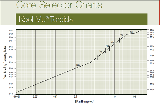
    I think that core is way too small (cm right?). Attached is a size chart from magnetics inc (http://www.mag-inc.com/) that will get you close in size. The current you use is your peak current. This is a different material - the one I use on most toroidal PFCs.


  • Hi Kevin.

    Thanks for the replay, yes dimensions are in CM. in reality I want a small inductor in order to meet PCB size, is it possible to use 2 stacked cores from the one I am using?

    I am able to draw 1150W from my PFC, I understand that the size is small, I have seen the size of the inductor for the 350W PFC in the AN.

    I would be grateful if you suggest me a core from those to order.

    How do I make sure if the inductor is causing problems into my PFC?

    Because it works just fine.

    one thing, do you have any suggested PCB layout to start with?


    Please advice


    Sami

  • Danel October Beriong said:

    It actually depends on the output power you want. I think the datasheet sample circuit is for 300W.

    I used the UCC28019A to make a PFC with 2kW output (~390V, ~5.2A). I tried using an ETD-59 core at first, but it was too inefficient, it saturated at 1400kW and it was almost impossible to put in more gap (because more gap, more turns, and i didn't have space left to do more turns because of the wire size). So I ended up using a toroidal core. Check out these cores: http://www.mhw-intl.com/wp-content/uploads/2011/10/CSC-Catalog-2011.pdf

    Mine is a CS610125 because of the 0.4mH requirement and high saturation current.

    Danel October Beriong


    Could you please confirm one thing, what is the final inductance value for your inductor (CS610125).

    ** Did you wind single layer or two layers of wire?

    ** Did you use Litz wire?

    ** How did you solve the OVP trigger issue in the UCC28019?

    ** Did you use any gate drive chip or driving the Mosfet directly from the UCC28019?


    I am still wondering the specifications for the PFC coil in the 350W Application note for (UCC28019)

    That coil it bigger that the one you are using, and you had success with 2kw


    Thanks in advance

    Regards