This thread has been locked.

If you have a related question, please click the "Ask a related question" button in the top right corner. The newly created question will be automatically linked to this question.

Issue with TPS40054

Other Parts Discussed in Thread: TPS40054

Hi,

I am sharath chandra working in Wipro technologies India.

I am using TPS40054 for the following applications in our design:

Input is : 30V (max)

1) 5V @ 8A

2) 5V @ 13A

3) 12V @3A.

For all the above voltages I am using TPS40054 (already designed and tested).

Issues:

1) Due to layout issues we have found that  the calculated ILim value is not meeting our current requirement, so we increased it and then it worked mainly for 5V @ 8A and 5V @13A.

But on one of the boards, in 5V @13A section while testing we increased the load from 0 to 13A, but when we reach to 8A it shuts down. and then the ouput voltage never comes again (even if we power OFF and ON it again). Then we replaced it with other IC, ame thing happened again (we tried four times).

We are not able to trace out the source of the problem. This is one which is killing our time, so please help us in this issue.

Note that we are facing problems in 5V @13A section only (even in other boards we had to replace the IC but it worked but it worked after replacing).


Thank you


Regards

sharath chandra


  • Hi Sharath,

    Can you share the schematic?

    Is the part damaged or it just cannot deliver 5V, 8A power due to fault protection?

    Can you capture the SS and SW waveform for review?

    Regards,

    Na

  • Hi Na,

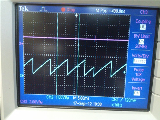
    I have attached the schematics and the screen shots of SS and SW pins. The SS pin shows that it is switching ON and OFF continuously.


    Note:

    We are in proto stage and the soldering is done manually in our Company. We have already tested 5V_13A for around 1 hour at 13A load and it worked fine.

    On one of the board we have connected 2200uF external capaciotr (to do capacitive loading test), while doing this test the output voltage sudeenly went to zero volts and from then we replaced the TPS 40054 IC thrice, but the same thing happens when we cross 8A load. 

    Note that we have seen the same problem in other boards that is, if there is an issue in 5V_13A section (due to MOSFET not soldered properly or the TPS40054  PAD not solder properly) by any reason, then even if we6177.Ti TI regarding TPS40054.doc replace the IC it does not support the full 13A load.


  • Hi Sharath,

    From the waveform, the TPS40054 is in hiccup mode for overcurrent protection. Since the ILIM resistor is designed for much higher overcurrent trip point, it is likely the OCP is tripped due to excessive ringing on SW node. By reviewing the schematic, I think there are something you could improve.

    (1) Add some 10uF or 22uF ceramic capacitors in parallel with the 100uF bulk (electrolytic) cap at the input. These input capacitors carry the pulsating current and need to have high RMS current rating. With a single electrolytic cap, the ESR is relatively large and the thermal stress on the cap will make it worn out easily. As the effective input capacitance drops, the ringing on the SW node will also get severe.

    (2) The 6.8-ohm snubber resistor (R2) seems a little bit high. The higher the resistance, less effective to lower down the SW spike. You may try to reduce it to 4.7ohm or 3.3ohm or even smaller. Of course if it is too small, then there is little damping and takes longer time for SW ringing to settle down. It will be a trade-off.

    (3) If the problem is still there, you may consider increase the high-side gate resistor R38 or SW resistor R30.

    The layout of PCB is also critical to make the part  part work. For example, the input power loop should be as short as possible. The bypassing capacitors should be close to their respective power and ground. The sensitive analog signal should be kept away from switching node. 

    I haven't check the loop design with the extra output capacitance. We have the spreadsheet for loop design which you may use to check your design (http://www.ti.com/litv/zip/sluc263c).

    If you still have problem, please feel free to let me know.

    Regards,

    Na

  • Hi Sharath,

    From the waveform, the TPS40054 is in hiccup mode for overcurrent protection. Since the ILIM resistor is designed for much higher overcurrent trip point, it is likely the OCP is tripped due to excessive ringing on SW node. By reviewing the schematic, I think there are something you could improve.

    (1) Add some 10uF or 22uF ceramic capacitors in parallel with the 100uF bulk (electrolytic) cap at the input. These input capacitors carry the pulsating current and need to have high RMS current rating. With a single electrolytic cap, the ESR is relatively large and the thermal stress on the cap will make it worn out easily. As the effective input capacitance drops, the ringing on the SW node will also get severe.

    (2) The 6.8-ohm snubber resistor (R2) seems a little bit high. The higher the resistance, less effective to lower down the SW spike. You may try to reduce it to 4.7ohm or 3.3ohm or even smaller. Of course if it is too small, then there is little damping and takes longer time for SW ringing to settle down. It will be a trade-off.

    (3) If the problem is still there, you may consider increase the high-side gate resistor R38 or SW resistor R30.

    The layout of PCB is also critical to make the part  part work. For example, the input power loop should be as short as possible. The bypassing capacitors should be close to their respective power and ground. The sensitive analog signal should be kept away from switching node. 

    I haven't checked the loop design with the extra output capacitance. We have the spreadsheet for loop design which you may use to check your design (http://www.ti.com/litv/zip/sluc263c).

    If you still have problem, please feel free to let me know.

    Regards,

    Na