This thread has been locked.

If you have a related question, please click the "Ask a related question" button in the top right corner. The newly created question will be automatically linked to this question.

TPS2590 startup bug(s)

Other Parts Discussed in Thread: TPS2590

We had a situation where the TPS2590 on our board was faulting, despite that the fault current value and current limit was set high enough that it shouldn't have been a problem.  What we found was happening was that the TPS2590 appears to be going into fault mode whenever it is current-limiting it's own internal series FET.  See the waveform below:  The voltage on Ct should only go up when the Iflt threshold is crossed, but it starts going up immediately upon power-on.  Nothing in the datasheet or functional block diagram give a hint that the FET protection circuit triggers a fault condition.

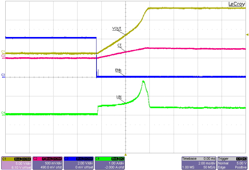
Another bug is that after FET protection circuit cuts out (when the FET is fully turned on), then the votage on Ct does stop rising, but it doesn't drop to GND very quickly either.  So if a real fault condition comes along, the Ct voltage does not start from ground, so the expected time delay won't be what was designed for.

Note: The chip is not in cofigured to be in retry mode, and because the chip didn't actually fault (the output voltage is still high), Ct voltage should quickly fall to gnd.  It actually looks like the chip thinks it has already faulted, and is using Ct to time when the next restart should happen.

Comments?


  • Phil, thanks for the feedback. I agree that key details are missing from the datasheet, and we are actively working to correct this.

    During power limited start up, the fault timer will be active. What we need to do is evaluate your circuit and adjust the ILIM, IFLT, and CT values to allow worst case start up. Please provide the following:

    1) What is your circuit load capacitance presented to OUT of TPS2590 (Cload in Figure 1 of the datasheet)? This impacts start up time and CT setting.

    2) What is your maximum expected operating dc load current? We would set IFLT (minimum) to be above this to avoid trips under normal circumstances.

    3) What is the load current at start up (the plot shows ~400mA)? This impacts the CT setting.

    4) Where do you want ILIM set at? Normally, ILIM minimum would be set above IFLT maximum.

  • It's not that key details are missing from the datasheet, the part is not working correctly.  The part should not go into a fault condition when it's power limiting while under the Iflt limit (which is the case here), and CT voltage should quickly fall so that the fault time delay can be what's designed for.

    Do you have an estimated date for a fixed part? 

  • Contact the local TI office/rep for generic inquiries.

  • Verified Answered?

    You didn't acknowledge that the part is indeed defective.  You didn't say when a corrected datasheet would be made available.  Nor when the part would be fixed.  What exactly did you verify or answer?

  • The part operates as designed and no revision is planned. A comprehensive datasheet re-work has been in queue for some time and really should have been online by now. I'll elevate the need for the revised datasheet to be available and post a reply when it's ready.