This thread has been locked.

If you have a related question, please click the "Ask a related question" button in the top right corner. The newly created question will be automatically linked to this question.

LM22677 12V 5A design ok?

Other Parts Discussed in Thread: LM22677

Hello,

maybe somebody can have a look to my design with the LM22677.

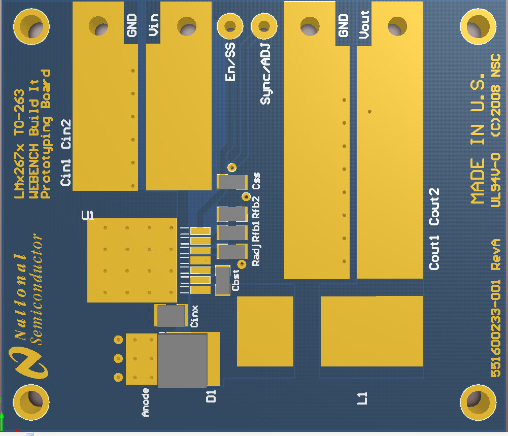
I use the webench for sizing the parts.0714.WebenchReportsServletlm22677.pdf


So here are my design:


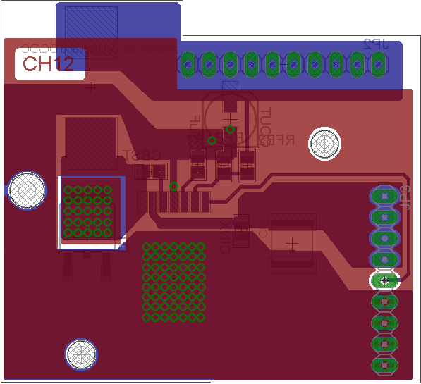
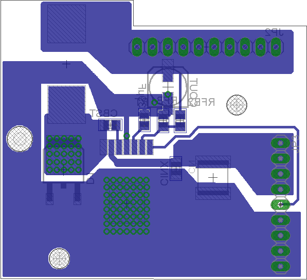
there will be a big passive heatsink mounted to the top layer.

Is this design ok? for the power?

Input is 21 -32V.

Kind regards

Christian

  • Hi Christian,

    Overall you layout looks good. In terms of improvement, I noticed one thing:
         I noticed you have thermal relief on the Cout pad, while this may make it easier to solder, it also makes this node have higher impedance. This could affect performance as this node is going to repeatedly handle around 1.7A according to your design. (maybe think about expanding the Cout ground pad for additional Vias)
         

    Below is a pic of the LM2267x build it board layout from WEBENCH. You will see that your layout is fairly similar but that more space is given to Cout ground. Also Cinx is placed on the other side of the IC to get as close as possible to the pin.

    Hope this is helpful,

    Best Regards,
    Tommy Jewell 

  • I have a big problem!

    I have only 5V at the output, why?