Hi,
where is the right position for R4?
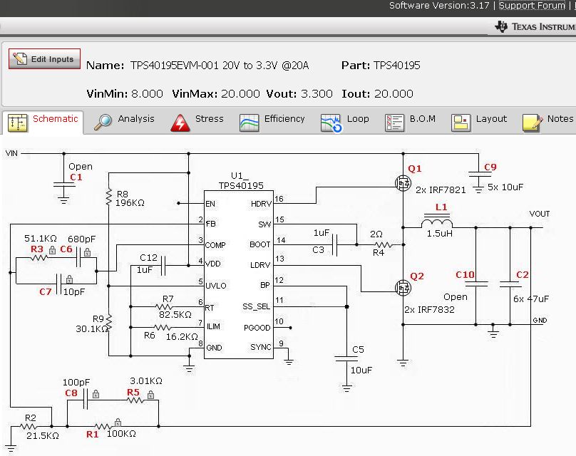
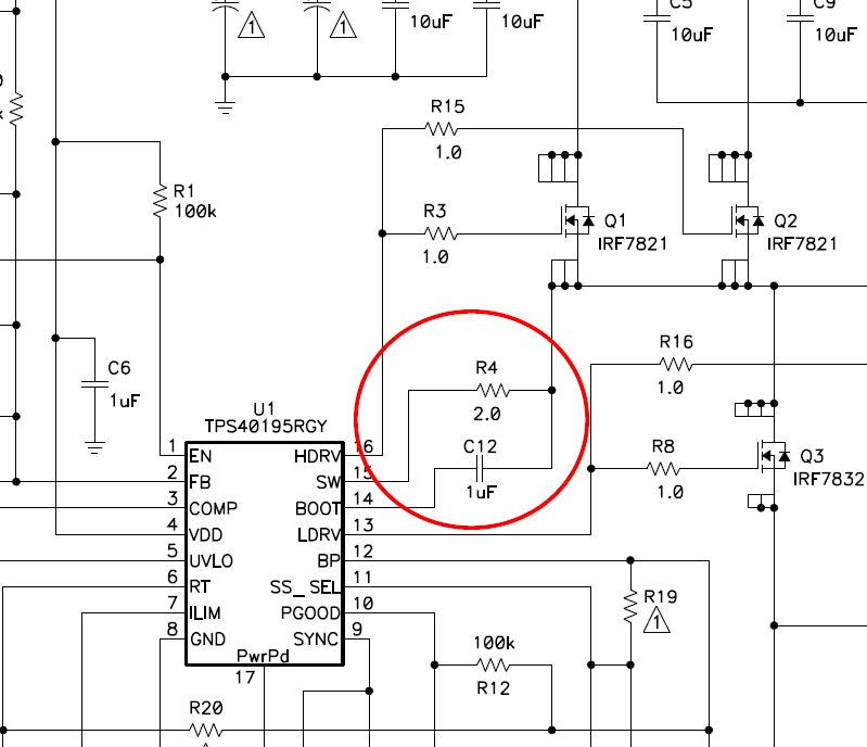
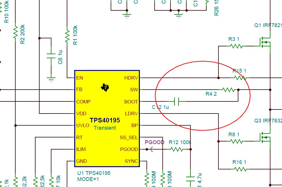
In Tina TI an The User Guide for the TPS40195EVM R4 is parallel to CBoost:

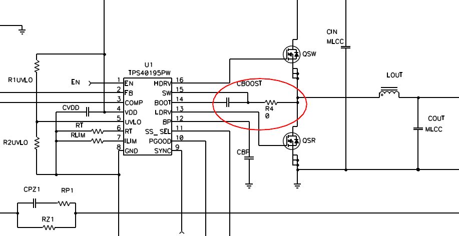
In datasheet R4 is serial to CBoost:
What's right?
regards
Andreas
Hi,
where is the right position for R4?
In Tina TI an The User Guide for the TPS40195EVM R4 is parallel to CBoost:
In datasheet R4 is serial to CBoost:
What's right?
regards
Andreas