This thread has been locked.

If you have a related question, please click the "Ask a related question" button in the top right corner. The newly created question will be automatically linked to this question.

TPS40210 General Questions Regarding Application

Other Parts Discussed in Thread: TPS40210

Hello folks,

I've got a couple of questions regarding the use of a TPS40210 in a somewhat brutal environment. This is an on-going R&D project for a company that I am consulting and don't want to divulge too many specifics, but I'll sketch the demands and then the good folks at TI can give me a slap upside the head, if necessary.

Application:

->Convert nominal 24V from 7 Ahr battery pack to 42 (maybe 46) V, 4 A "pulsed" output - current will only be drawn for short periods at a very low duty cycle

->The output needs to be approximately constant current (+/- 0.5 amp), not constant voltage and needs to swing from short circuit protection state (0V, 4 A) to the full output, 42 V 4A

->In a typical year, the device will only be operating for a total time of 24 hours but could be exposed to temperatures ranging from -10*F to 130*F and the equipment is portable, so shock/vibration are likely

->Cost should be kept at a minimum without sacrificing reliability. The electrical performance can be sacrificed, e.g. the voltage and current can ripple quite a bit; regulation can be within +/- 0/5 amp, etc

>>> During typical operation, I only need about 12 volts to maintain 4 amps but occasionally, I need up to 42 volts to maintain 4 amps. Unfortunately, these current bursts only last about 10 milliseconds so whatever solution I come up with has to respond fairly quickly. I do have a micro-controller at my disposal. I considered using this to enable/disable the TPS40210, but I'm not sure how quickly this will respond (e.g., the micro-controller turns on the output, detects a high resistance load and tells the TPS40210 to turn on. Then the TPS40210 has to turn on and supply a 4 amp pulse all within a about a millisecond).

Questions:

1) What is the best way to implement a constant current design? Before investigating the possibility of using the TPS40210, I had designed a very simple method of regulating current using a TIP142G, a current sense resistor, a differential amplifier and a general purpose NPN transistor. At 24 volts, I was able to produce a circuit that regulated the current to an average 3.8 amps without ever asking the transistor to dissipate more than 125 watts. I can tack this on to the output of the TPS40210 if necessary, but this leads to my second question:

2) If I tack my little "constant" current circuit onto the output of the TPS40210, is there a way to adjust the voltage output? For instance, as my differential amp turns on the general purpose NPN transistor, it shorts current from the base of the TIP142G causing it to turn off. Can I also control another resistor to pull the comp pin low? Would this drop the voltage in a predictable manner? Alternatively, can I inject my own voltage to the feedback pin to control the voltage? The idea here is to drop the output voltage to, say, 30 volts when the load resistance drops below a certain threshold. This will help prevent the TIP142G from having to dissipate too much power.

(As you've probably guessed, I'm just pretending to be an EE. By profession I am a physicist so I apologize for any abuse of terminology and for my rube-goldberg style approach!)

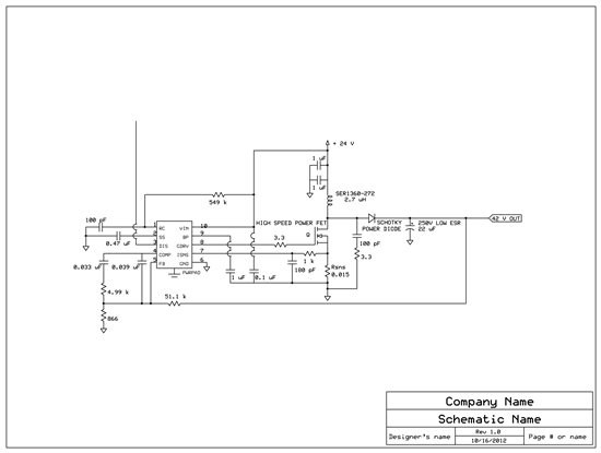
Here's the circuit (I've chosen components based largely on cost. The output ripple is fairly low allowing the use of a single, fairly cheap capacitor. The trade off is an increased input ripple current, which is handled by two cheap X7R ceramic capacitors with a high ripple current rating). I hope this looks like a reasonable design...

  • Hi Tom,

    Thank you for the detailed description of your application. At a quick look everything looks reasonable. Please see below for some of my thoughts on your comments/questions and the application.

    ->You may need to increase the output capacitance to help supply the pulsed current. But this will depend on how quick your transient is.

    ->If you do not need constant voltage regulation at all, constant current with the TPS40210/1 is typically done by putting the low side FB resistor in series with the output load. If you haven't looked into this already please see Figure 29 in the datasheet for an LED driver example. Depending on what the load looks like I'm not sure if this will work in your application. Alternatively the tracking circuit you have sounds like it will work fine.

    ->If you plan to control the TPS40210 with the DIS/EN pin the requirement for short turn on is where it might not fit. Is possible in your application to predict the turn on of the TPS40210 in advance? The internal turn on sequence of the device has some delays the main being an ~2.5 ms delay from the EN signal to the BP regulator powering up. Putting this capacitor at the minimum will speed it up. The slow start voltage will then rise based on your slow start capacitance. Additionally the 700mV offset of the slow start ramp can add more delay. Some of this can be overcome by placing a resistor in series with your slow start capacitor. The max value of 24.9kΩ is recommended and you can see the EVM uses a 10kΩ.

    If your not worried about overshoot during startup you may be able to disable/enable the regulation of the TPS40210 using the COMP pin instead but this can hurt the battery life keeping the controller on continuously. You will also lose the slow start and can have overshoot when returning to regulation.

    ->Lastly to answer your second question, you can cause the output voltage do drop by pulling COMP to GND. Once it is pulled low enough the device stop switching and the output will decay based on your load current and the charge on the output capacitance. You can also use a voltage at the FB pin to adjust the regulation point. You can do this by using a series resistor with the injected voltage to inject a current. Take a look at the following application note for an example of this: http://www.ti.com/lit/an/slva251/slva251.pdf

    Hope this help you out. Let me know if you have any additional questions.

    Regards,
    Anthony

  • Thanks Anthony!

    It sounds like I am on the right track. At least I know I won't immediately let the magic smoke out of the TPS40210 when I put it on a breadboard. I did have a look at the LED driver in the data sheet but I'm not sure how well it work in my situation. I was concerned with the fact that the current isn't continuous and, more importantly, there is some additional hardware on the ground side of the load which would complicate matters.

    Just to clarify, is it reasonable to attempt to control the output voltage of the controller with my tracking circuit? E.g., instead of controlling the power transistor, I regulate the voltage from the controller either by injection or playing with the COMP pin until I hit some minimum voltage, say 28 V. Below 28 V, the regulation will be accomplished by the power transistor. 

    It sounds like trying to enable/disable the TPS40210 from pin 3 will take too long, as I feared. Could you provide me with any qualitative guesses as to how fast I can turn it on from the  COMP pin and also a qualitative feel for how much overshoot I would experience? I will put it on a board and test it soon, so no need for details, but an intuition would be appreciated!

    By the way, the battery life is not too big of an issue. It typically gets used for about 30 minutes before being recharged. That's why I'm not too worried about regulating the current with a transistor and dissipating a bunch of power ... efficiency is not a concern. This piece of equipment is sort of a dinosaur by modern standards, I think.

    Thanks again!

  • Hi Tom,

    This is definitely a reasonable way to accomplish this. It is similar to how you would regulate an isolated flyback with an optocoupler. The optocoupler output drives the FB pin or the COMP pin to adjust the peak current accordingly to keep the supply in regulation. One of the main difference here is how you compensate your control loop.

    I don't really have a good guess how much the output voltage would overshoot by allowing the voltage to rise using the COMP pin. My best thought is it would end up being a function of your output capacitance and control loop bandwidth. You would also need to be careful of running into current limit issues during this turn on transient so you may need to limit the rise rate of the COMP voltage depending.

    Regards,
    Anthony