This thread has been locked.

If you have a related question, please click the "Ask a related question" button in the top right corner. The newly created question will be automatically linked to this question.

UC3823N boost converter works in DCM??

Hi, I designed a boost converter using UC3823N. I got a problem that no matter how adjust parts' values, the converter still works in DCM. If I increase load, the power supply of boost converter would go to current limit and decrease supply voltage(current limit of power supply is 3.2A).

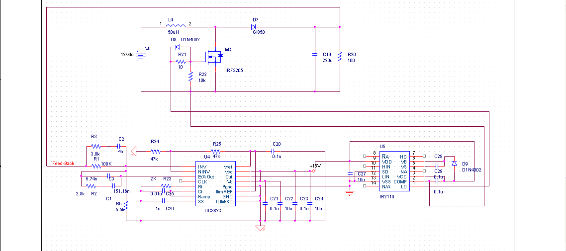
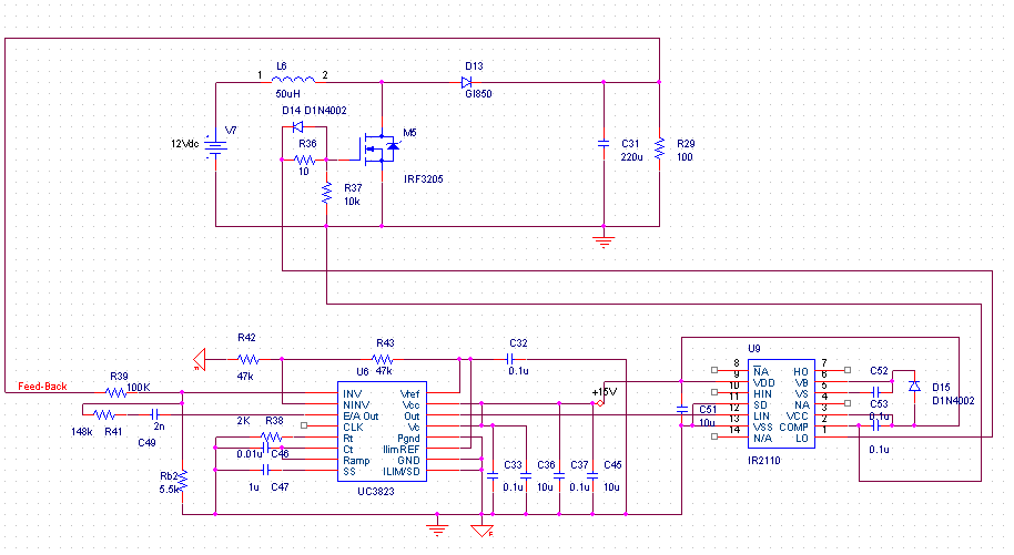
Here are parameters: input voltage 12V, output voltage 48V, PWM duty cycle, output current 2.5A(variable  load). I built my circuit on a breadborad, the following schematic is my design,

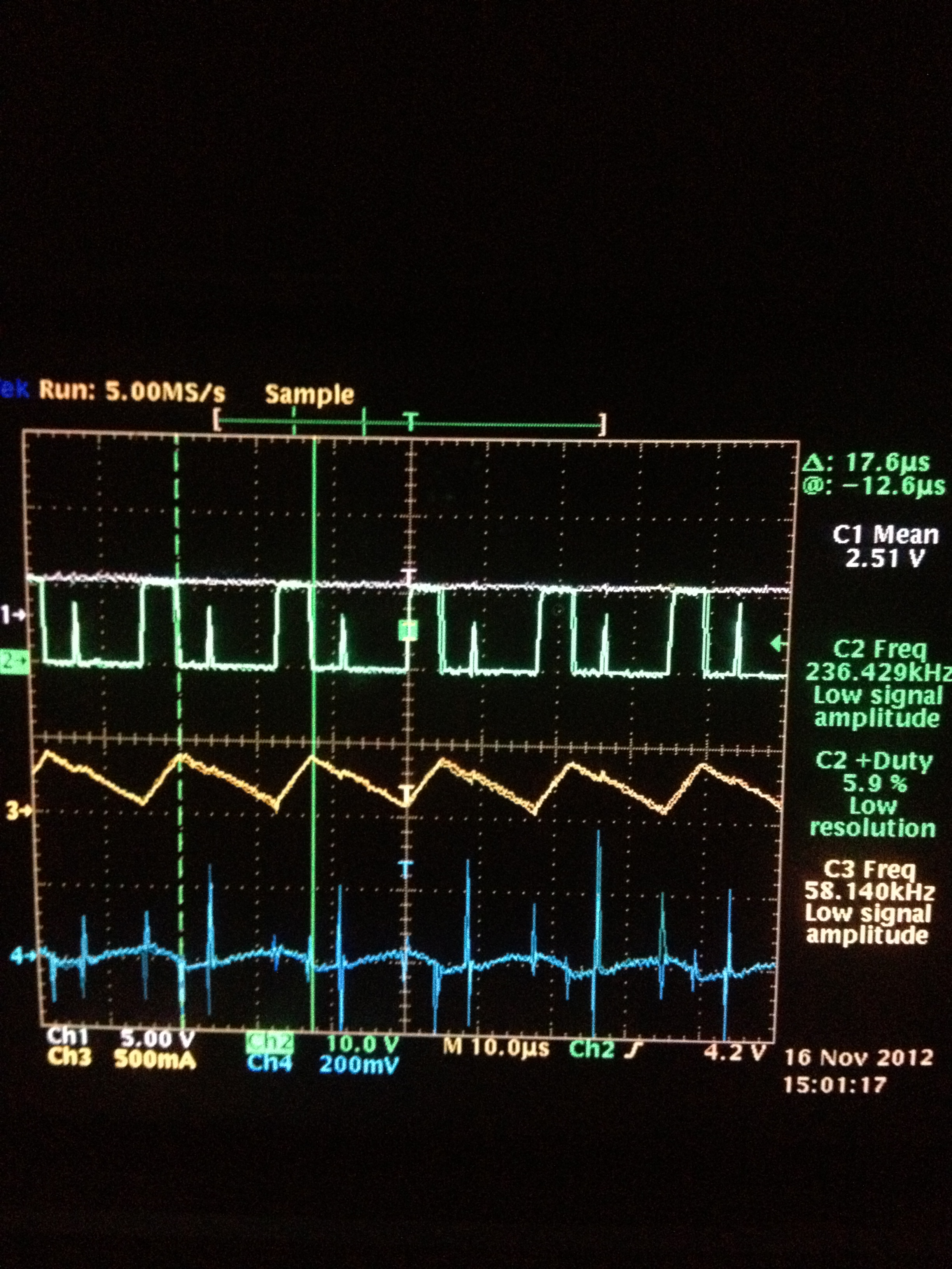
The following picture is some values of pins on UC3823N

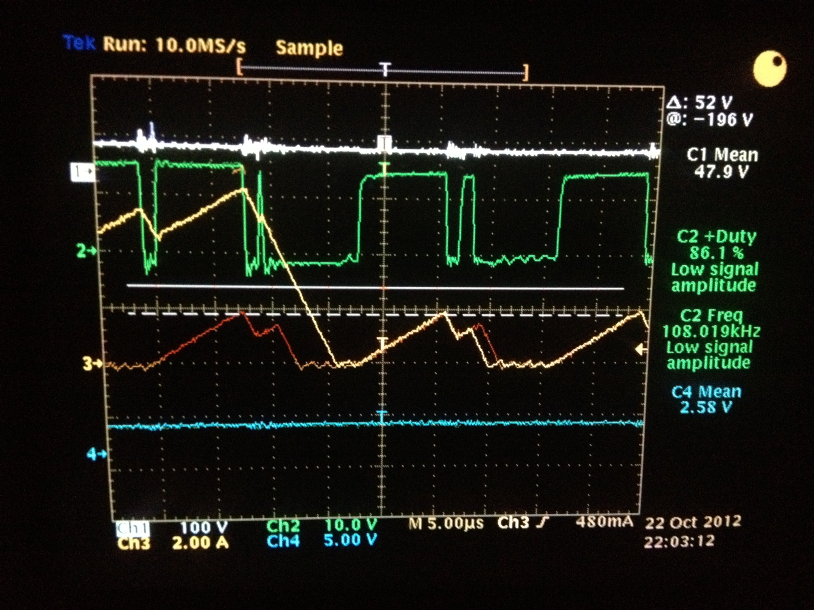
The white line in the above picture is output voltage, the green line is output PWM of UC3823N(I know it's weird), the yellow line is input current of boost converter(it's "jumping"). The blue line is voltage on Pin 1(Inv) while the voltage on Pin 2(NI) is one half of reference voltage(pin 16), which is 2.55V.

Another interesting problem is that, if I use potentiometer to increase voltage on pin 1, the output PWM duty cycle would drease, and so does the freqency of PWM. In my design, I choose RT and CT to let UC3823N works at about 100K Hz. If the output duty cycle decreases to 30%, the frequency would also decrease to 50K Hz.

Please help me to figure out my problem.

He, Siyu

  • Hi Siyu.

    For what I'm seeing, and looking to fsw and selected inductance value, you could have instability in your control loop...

    It' completely strange to have more than 6Amps input current while your output voltage is stable...

    Where do you put your crossover frequency?

    Remember that working in CCM you have a RHP zero to that needs to be compensated...

    From my calculation, it could be somewhere around 1.5kHz.

    Your closed loop crossover frequency must be at least one decade lower...
    I would try to focus on control loop...

    Bye

    Paolo

  • Hi, Paolo

    The schematic I posted is just to check whether the circuit works right. Before this, I used another set of compensator values, here comes the previous schematic

    In this control loop, the compensator has two poles and two zeroes and one pole at origin, I set crossverfrequency at 2K Hz. You mentioned that, closed loop crossover frequency must be at least one decade lower than the frequency of RHP zero. For my example, the RHP zero is at 1.5KHz, the crossover freqency should be less than 150Hz, is this calculation right?

    He, Siyu

  • Hi,

    Would you mind give me the formula you used to calculate RHP zero frequency?

    I looked up in textbook, the RHP zero in boost converter transfer function is (1-s*Le/R), in which Le equals L/(1-D)^2, R is load resisitor. In my circuit, the inductor is 50uH, load is about 100 ohms. From my calculation, RHP zero is at 125K Hz.

    Take one decade lower, crossover frequency should be lower than 12.5K Hz, I choose 2K Hz in my design.

    Thanks for your time.

    He, Siyu

  • Hi Siyu.

    I think you've to compensate for the worst case RHP, and if you told me that your output is 48V@2.5A your equivalent load is much more lower than 100Ohms.

    It should be something like 19.2 Ohms.

    With this figure, your RHP is much more lower and it is really close to your crossover frequency.

    I continue to think you've lo tower your fc to obtain good results...

    Otherwise, you could think to work in DCM in order to avoid all this problems...

    Have a nice day

    Paolo

  • Hi Paolo,

    I am sorry that, 2.5A is input current, I read that on the power supply and output is connected to a variable load, so I just adjust load to about 100 ohms. I will take your advise to lower my crossover frequency,  I need to make it work in CCM.

    I  have another question about compensation loop, is it neccessary to take voltage divider gain(connected to UC3823N as feedback, divide output 48V to 2.5V) and PWM gain(which is calcualted as 1over peak-peak value of ramp signal) into loop gain calculation? I got different answers from different textbook and T.I. application note.

    He, Siyu

  • Hi Siyu.

    Sorry for the misunderstanding!

    Obviously yes, I've to take in account everything included in your control loop, so the PWM modulator gain too...

    Have a nice day

    Paolo

  • Hi, I tried to lower crossover frequency to 1K Hz, however it still works in DCM and output voltage can not reach reqirement. I noticed that the voltage of Pin1 of UC3823N is about 1.7V,  voltage on Pin 2 is 2.5V , voltage on Pin 3 is about 5V. The interesting thing is that the output PWM duty cycle is about 43%. I suppose that the output PWM should be maximum, about 85%, while Pin 3(E/A out) is about 5V.

    Would you help me with that?

    Thanks,

    He, Siyu

  • Hi, Paolo

    I have a thonght, would it be the reason that I connect the ouput of UC3823N to IR2110 to drive mosfet? However, I use a function generator to input 75% PWM  to IR2110, the output is 48V and boost converter works in CCM. Does this trial eliminate the possibility that faults would be around IR2110?

    He, Siyu

  • Hi Siyu.

    To be honest, it's really strange!

    With the divider you set on you INV pin you must have 2.5V when your output is at 48V...

    I don't think that the problem is your post driver, it is in your PWM controller...

    Are you sure that your duty cycle is limited only by voltages and not by current limit settings?

    Looking the DS, this could be the only other reason...

    Bye

    Paolo

  • Hi, Paolo,

    I connected Pin 11(ILIMREF) to Pin 16(Vref 5.1V) and I use voltage mode control only.

    Maybe i misunderstood the usage of pin 11 and make my circuit work in current mode by fault. Would you mind tell me how to deal with pin 11 in voltage mode control?

    What do you mean by the "DS"? Is it voltage accross drain and source of mosfet?

    I really appreciate your help.

    He, Siyu

  • Hi Siyu.

    I was meaning DataSheet...

    However, with a boost working in continuous mode I think it's better to run a current mode control, it's more robust...

    In voltage mode you've to put your crossover frequency lower than now...

    About the use of this IC in voltage mode, I'm sorry, I've no experience with this IC and I'm used to work in current mode, I can't help you from this point of view, but, always from datasheet, maximum allowable voltage on pin 11 seems to be 1.55V, putting 5V or more probably put your IC in a condition in which it's not so happy...

    Bye

    Paolo

  • Hi, Paolo

    Thanks for your advice, I know it is kind of out of date to use voltage mode.

    Would you mind give me some application note about how to how to fullfill current mode control?

    He, Siyu

  • Hi Siyu.

    Unfortunately, I can't suggest you anything because I usually follow indication coming from my university hand written notes...
    However, I remember that on the TI website there are a lot of appication notes and seminars made at the time when they were still Unitrode, there you can find everything about current mode control (for you low power application I suggest peak current mode).

    Good luck!

    Paolo

  • Hi, Paolo.

    I tried current control mode, but the same problem still occures. The following is captured from scilloscope.

    The output voltage is adjusted around 17 V. Ouput PWM duty cycle should be around 30%.When I test it in open loop, the control chip works at 116K Hz frequency.

    The data in the image above is collected when circuit works in closed loop. The problem is that output PWM composed a wide pulse about 4.8 us(about 55.81% duty cycle based on 116K Hz) and a spike with same magnitude of pulse. I believe this spike is the initial of a sequence PWM.

    I am wondering why can't PWM output be 30% duty cycle for each periode?

    The bottom line (blue) is the voltage of current sense? Why it does not follow the ramp of input current which is in yellow in above image?

    He, Siyu