This thread has been locked.

If you have a related question, please click the "Ask a related question" button in the top right corner. The newly created question will be automatically linked to this question.

LM5117: Bad current ripple at certain current draw

Other Parts Discussed in Thread: LM5117, LM358, TINA-TI

Hi,

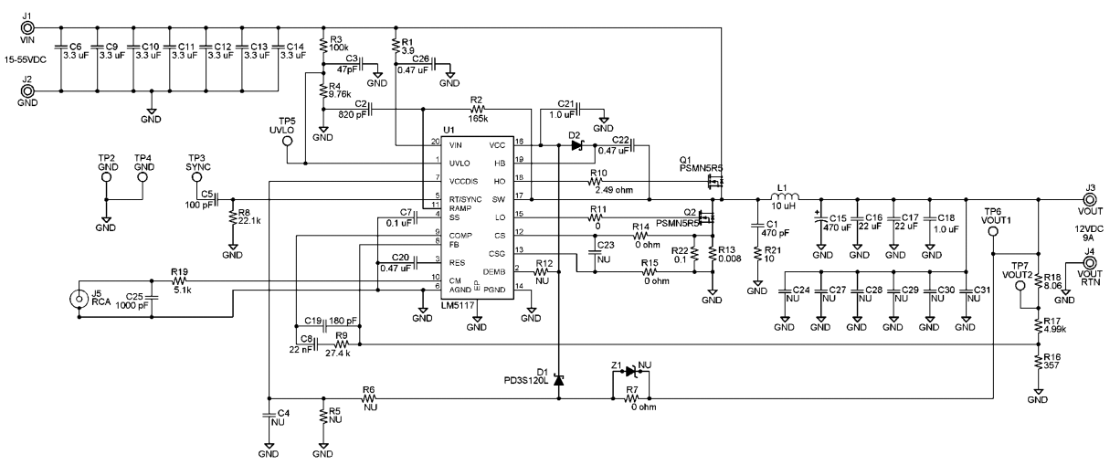
I'm using the evaluation board for the LM5117 and changed some components to these values with the help from WEBench and the excel calculator. I kept the other components as is. I'm trying to optimize the circuit to output 12V at max current of 2A, from input voltage of 36V to 60V. 

L1 - 47uH, DO5040H-473MLB, Coilcraft as recommended by webench

C15 - 47uF, 55 mohm

R3 - 54.9k

R4 - 2.32k

R9 - 30k

C8 - 18nF

C19 - 56pF

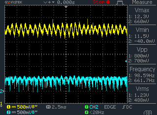
I observed that when I use my electronic load to increase the current drawn from the DC-DC regulator from 0A to 2A, there is a huge output current ripple (400mA) at around 500mA output, see below scopeshot. I probed the CM output using my voltage probe as I do not have a current probe at hand. The ripple is only observable from 300mA to 500mA range. Once outside this range, the ripples are not noticeable. 


Ch1 - Voltage output

Ch2 -  Voltage output of CM (via J5 connector)

Input voltage: 48V

I've tried varying the output capacitance but to no avail though at low cap value, the output voltage has a noticeable ripple of 200mV but as I increased the cap, it lowers down to about 100mV but the current ripple is still there. I thought it could be the compensation circuit but I followed the excel correctly. Could you throw some ideas on what could cause this ripple and what are the things I can do about it? 

Thanks in advance!

  • I want to add that I do not have a network analyzer. What I have is just a 100MHz oscilloscope and a couple of DMMs. The electronic load is self made from an opamp (LM358) and a Darlington transistor with power resistor. 

  • Hi

    Loos like it is unstable. Please try R9=4k, C8=100n and C19=470p. I  assume R17=4.99k.

    Regards,

    Eric

  • Hi Eric,

    Thanks for the help. I will try it once the components come in and let you know how it goes.

  • Hi Eric,

    The result got much more worse. Here's the plot. 

    Please advise. 

  • Hi Winston

    At least, we found that the issue was related with loop response.  Please show me your schematic. I can try simulation.

    Regards,

    Eric

  • Hi Eric,

    I'm using the evaluation board from TI so it's basically the same as theirs except for those components that I've changed:

    L1 - 47uH, DO5040H-473MLB, Coilcraft as recommended by webench

    C15 - 47uF, 55 mohm

    R3 - 54.9k

    R4 - 2.32k

    R9 - 30k

    C8 - 18nF

    C19 - 56pF

    R8 - 18.7k

    Here is the circuit: (Literature Number: SNVA466A)

    Could you tell me what software are you using to simulate so I could do it on my own?

    Thanks

  • Hi Winston.

    I agree with other colleagues...

    Probably your control loop is not so stable...

    Looking to R8 I can imagine you're working at 200kHz, more or less...

    Where do you put your closed loop crossover frequency?
    Which is you ramp amplitude?

    With these data I can suggest you which could be a more robust compensation...

    Bye

    Paolo

  • Let me add: there's could be something wrong in your current sense circuit!

    From DS I can see that the current sense threshold is set to 0.12V.

    If you want 2A on your output it is reasonable that your peak current will not exceed 2.5-3A...
    With the resistor you put in your schematic (0.1 Ohm in parallel to a 0.008 Ohm) your threshold is never reached!!!!

    You're trying to work with a current mode control, but you're not controlling current...

    Bye

    Paolo

  • Hi Paolo,

    I'm working at 264.658 kHz (blame webench for the weird number). 

    I'm not sure how do find my closed loop crossover frequency and ramp amplitude. Could you point to me on how to get these data? I do not own a network analyser and I only have a 100 MHz scope. Please advise.

    My mistake, I forgot to let you know that I also changed R22 and R13 to a total of 40 mohm. 

    Thanks,

    WInston

  • Hi Winston.

    Closed loop crossover frequency has to be set by yoy by design.

    If you work at 264kHz it could be reasonable to put it not more than 50kHz.

    Ramp amplitude is necessary to know which is your open loop gain...

    Probably you can measure it directly on the IC's pin...

    Let me know this number and I'll provide you a compensation network...

    Bye

    Paolo

  • Hi Paolo,

    I designed my closed loop crossover frequency to be at 26.4 kHz. 

    I measured my ramp amplitude to be at 350mV. 

    Thanks,

    Winston

  • Hi Winston.

    First of all, I will try to increase your current sense resistor...
    @264kHz with a 47uH inductance you should have something in the range of 2.5Apeak...

    A 47mOhm resistor has to be considered...

    With your number, I can suggest you this compensation network in order to maintain your 26.4kHz desired crossover frequency:

    R9=8.2kOhm

    C8=330nF

    C19=6.8nF

    Please, try in this way and let me know if something changed...

    Bye

    Paolo

  • Hi Paolo,

    Regarding the current sense resistor, if I increase the value to 47 mohm, my max current limit will decrease meaning there are higher chances the LM5117 will cut off the power during load transient where the current will max momentarily, am I right? 

    Thanks for the new compensation values. I will try it once my parts come in. Before that, could you explain to me how did you get it? Did you use the TINA-TI or SwitcherPro to get the value? I would like to know how you get this value so I can calculate on my own. 

    Thanks,

    Winston

  • Hi Winston.

    If you think that 47 mOhm are too much for your application and you need more margin for your transitions you can think to low it to 39-33mOhm, not more, otherwise your current mode control in uneffective...

    I don't use any particular software to calculate values, I've designed an excel sheet that depending from circuit parameters and oscillator ramp give me as a feedback the open loop crossover frequency, then I only need to choose my desired crossover frequency and all the compensation network data are given me as a feedback...

    Bye

    Paolo