This thread has been locked.

If you have a related question, please click the "Ask a related question" button in the top right corner. The newly created question will be automatically linked to this question.

BQ78PL114S12 Hardware Short Circuit Detection doesn't trigger

Other Parts Discussed in Thread: BQWIZARD, BQ78PL114

Hi

I am using a BQ78PL114S12 (FW 5000) and a 4S2P Li- Ion battery pack with 4400mAh. I'm still configuring the device. Today I wanted to configure the Hardware Short Circuit Protection. I thought, this would be done quickly, but I was wrong. Although I think, I've set the values for the Hardware Short Circuit Protection, properly it never gets triggered (HSC Flag not set). Instead the 10A slow blow fuse evaporates. For testing I use a 0.68Ohm 17W resistor, because I don't  want to directly short out the battery. When "shorted out" via this resistor, the pack delivers nearly 24A. This current develops a voltage drop of approx. 240mV across the 10mOhm sense resistor. This current is properly displayed in bqWizard. Sure it clips at -20A because of the 10mOhm Sense- Resistor and a gain of 5.

The Hardware Short Circuit registers are configured as follows:

Hardware Short Circuit threshold: 47

that means it should trip minimum at 12.6A and maximum at 16.8A if I'm not wrong?

Hardware Short Circuit recovery: 15

Hardware Short Circuit Time: 3

HSC Max Attempts: 1

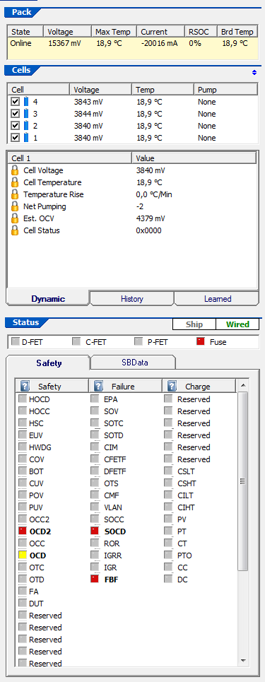
So If I short out the battery pack via the 0.68Ohm load resistor, all other overcurrent discarge flags are set (Tier1 Tier2 ) but the HSC isn't triggered.

I don't understand where the problem is. Maybe the hardware shortcircuit detection is dependend from any other registers, although there is nothing written about it in the technical reference manual.

Please help!

Kind regards

Gregor

  • Gregor,

    Are you really using a 680 mohm sense resistor? I am not sure that the device can be configured to work with a sense resistor that large. The thresholds were designed to work with resistors in the 1 to 10 mohm sense resistors.Can you lower the value?

    Regards

    Tom

  • Oh you've misunderstood me. I am using a 10mOhm sense resistor. I use a 0.68Ohm resistor as a load resistor to simulate a short circuit, without exceeding the battery's discharge current limit which is 25A. In my application I will have max. 6A current continiously flowing. So 12.6A to 16.8A is a good threshold value for short circuit detection in this case.

    Here are my configurations for safety level 1

    The whole configuration can be seen here

    [System Parameters]
    <SBData Dynamic>
    Pack Voltage;15410;mV
    Current;0;mA
    Average Current;0;mA
    Temperature;16,7;�C
    Absolute State of Charge;29;%
    Relative State of Charge;57;%
    Full Charge Capacity;2239;mAh/10mWh
    Remaining Capacity;1277;mAh/10mWh
    Run Time To Empty;65535;Minutes
    Average Time To Empty;65535;Minutes
    Average Time To Full;65535;Minutes
    Battery Status;0x4880
    Cycle Count;0;Cycles
    At Rate Time To Full;65535;Minutes
    At Rate Time To Empty;0;Minutes
    At Rate Ok;65535
    Max Error;10;%
    
    <SBData Static>
    Manufacturer Access;0x55AA
    Manufacturer Name;TEXAS;INSTRUMENTS
    Device Name;bq78PL114
    Device Chemistry;LION
    Manufacturer Data;0E4D616E20446174612020202020200000000000000000000000000000000000
    Serial Number;1
    Manufacture Date;03/20/2009
    Specification Info;49
    Design Voltage;16800;mV
    Design Capacity;4400;mAh/10mWh
    Charging Voltage;0;mV
    Charging Current;0;mA
    At Rate;0;mAh/10mWh
    Battery Mode;0x6001
    Remaining Time Alarm;10;Minutes
    Remaining Capacity Alarm;0;mAh/10mWh
    
    <Pack Dynamic>
    Board Temperature;16,7;�C
    Pack Passed Current;-322;mAh
    Cycle Since Learn;0
    Epoch Hour;0
    Temperature Voltage Trim;1,000
    FET Status;0x0080
    Safety Alert;0x2800
    Safety Status;0x0800
    Safety Alert1;0x0000
    Safety Status1;0x0000
    Permanent Disable Alert;0x8800
    Permanent Disable Status;0x8800
    Charge Alert;0x0000
    Charge Status;0x0000
    Number of Rebuilds;0
    Number of Polls;1394
    Number of Poll Errors;0
    
    <Charge Control>
    Pre-Charge Temperature;0,0;�C
    Pre-Charge Voltage;3000;mV
    Pre-Charge Recovery;3100;mV
    Pre-Charge Current;240;mA
    Charge Inhibit Temperature Low;0,0;�C
    Charge Inhibit Temperature High;45,0;�C
    Charge Inhibit  Recovery Temperature Low;5,0;�C
    Charge Inhibit Recovery Temperature High;40,0;�C
    Charge Suspend Temperature Low;5,0;�C
    Charge Suspend Recovery Temperature Low;10,0;�C
    Charge Suspend Temperature High;60,0;�C
    Charge Suspend Recovery Temperature High;55,0;�C
    Charge Completion Pack Voltage Qualifier;16800;mV
    Charge Completion Taper Current Qualifier;275;mA
    Charge Completion Time;20;Seconds;RDTE
    Charge Completion FET Activation Time;10;Seconds;RDTE
    Discharge Completion Pack Voltage Qualifier;12000;mV
    Discharge Completion Time;4;Seconds;RDTE
    Discharge Completion FET Activation Time;6;Seconds;RDTE
    Discharge Under Temperature;-10,0;�C
    Discharge Under Temperature Recovery;0,0;�C
    Discharge Under Temperature Time;2;Seconds;RDTE
    FC Set SOC Threshold;5;%
    FC Clear SOC Threshold;1;%
    FD Set SOC Threshold;5;%
    FD Clear SOC Threshold;1;%
    FD Set Voltage;12400;mV
    FD Clear Voltage;12800;mV
    FD Set Voltage Time;0;Seconds
    Transition to Idle Current;50;mA
    Transition to Idle Time;30;Seconds
    Transition to Discharge Current;-75;mA
    Transition to Charge Current;75;mA
    Cell Shutdown Voltage;2500;mV
    Design Capacity mAh;4400;mAHrs
    Design Capacity 10mWh;69120;mWh
    TDA Set SOC Threshold;-1;%
    TDA Set Voltage Threshold;12800;mV
    TDA Set Voltage Time;0;Seconds
    TDA Clear SOC Threshold;-1;%
    TDA Clear Voltage;14800;mV
    TCA Set SOC Threshold;-1;%
    TCA Clear SOC Threshold;-1;%
    OCA Set Voltage;17400;mV
    OCA Activation Time;2;Seconds;RDTE
    
    <Pack History>
    Lifetime Minimum Pack Voltage;15406;mV
    Lifetime Maximum Pack Voltage;15413;mV
    Lifetime Minimum Cell Voltage;3850;mV
    Lifetime Maximum Cell Voltage;3855;mV
    Lifetime Maximum Charge Current;73;mA
    Lifetime Maximum Discharge Current;-15813;mA
    Lifetime Delivered Amp Hours;0;Ah
    Last Discharge Average;-480;mA
    Lifetime Minimum Temperature;16,7;�C
    Lifetime Maximum Temperature;17,4;�C
    Lifetime Maximum Power;0;Watts
    
    <Cell Balancing>
    Cell 1 Net Pump;0;Pumps
    Cell 2 Net Pump;0;Pumps
    Cell 3 Net Pump;0;Pumps
    Cell 4 Net Pump;0;Pumps
    Cell 5 Net Pump;0;Pumps
    Cell 6 Net Pump;0;Pumps
    Cell 7 Net Pump;0;Pumps
    Cell 8 Net Pump;0;Pumps
    Cell 9 Net Pump;0;Pumps
    Cell 10 Net Pump;0;Pumps
    Cell 11 Net Pump;0;Pumps
    Cell 12 Net Pump;0;Pumps
    Minimum Cell Differential For Balancing;10;mV
    
    <Cell Chemistry>
    Chemistry ID;101
    Aux Chemistry Version;0
    Tau10;225
    Normalized Dynamic Impedance Low Temperature;20,0;�C
    Normalized Dynamic Impedance High Temperature;40,0;�C
    Normalized Dynamic Impedance SOC;15;%
    Normalized Dynamic Impedance Gain;32
    FCC Learn Qualifier;5;%
    Cycle Fade;0,05;%
    Min OCV Slope;2;mV/%;RSOC
    OCV Idle Qualifier;30;Minutes
    Stale FCC Timeout;2880;Minutes
    Default Charging Voltage;16800;mV
    Default Charging Current;2500;mA
    Capacity Algorithm;0x0003
    User Rate;1000;mA
    Current Delta;100;mA
    
    <Pack Configuration>
    Hardware Configuration;0x0731
    Algorithm Enable;0x000E
    System Control;0x0000
    Parallel Count;2
    Expected Number of Cells;4
    Actual Number of Cells;4
    Max Number of Cells;12
    Temperature Sensor Count;1
    Max Number of Temperatures;13
    Sense Resistor;10000;uOhms
    EPD Refresh Period;10;Minutes
    EPD Pump Time;120;Cycle;Counts
    EPD Write Time;70;Cycle;Counts
    Display Driver Frequency;30;Hz
    FW Build;12
    Firmware Version;5000
    Access Level;2
    
    <Safety Level 1>
    COV Threshold;4250;mV
    COV Recovery;4100;mV
    COV High Temperature Threshold;4250;mV
    COV High Temperature Adjust;50,0;�C
    COV Time;2;Seconds
    CUV Threshold;2700;mV
    CUV Recovery;3000;mV
    CUV Time;1;Seconds
    POV Threshold;17000;mV
    POV Recovery;16400;mV
    POV Time;6;Seconds
    PUV Threshold;11200;mV
    PUV Recovery;12000;mV
    PUV Time;1;Seconds
    EUV Threshold;2500;mV
    EUV Time;2;Seconds
    EUV Recovery;2900;mV
    OC Charge Tier 1 Threshold;4800;mA
    OC Charge Tier 1 Recovery;2;Seconds
    OC Charge Tier 1 Time;6;Seconds
    OC Discharge Tier 1 Threshold;-7200;mA
    OC Discharge Tier 1 Recovery;2;Seconds
    OC Discharge Tier 1 Time;8;Seconds
    OC Charge Tier 2 Threshold;5200;mA
    OC Charge Tier 2 Recovery;8;Seconds
    OC Charge Tier 2 Time;2;Seconds
    OC Discharge Tier 2 Threshold;-9600;mA
    OC Discharge Tier 2 Recovery;8;Seconds
    OC Discharge Tier 2 Time;1;Seconds
    OC Max Attempts;3
    Hardware OC Charge Threshold;211
    Hardware OC Charge Recovery;1;Seconds
    Hardware OC Charge Time;60
    Hardware OC Discharge Threshold;39
    Hardware OC Discharge Recovery;100;Seconds
    Hardware OC Discharge Time;20
    HOC Max Attempts;3
    Hardware Short Circuit Threshold;37
    Hardware Short Circuit Recovery;15;Seconds
    Hardware Short Circuit Time;3
    HSC Max Attempts;1
    OT Charge Threshold;50,0;�C
    OT Charge Recovery;45,0;�C
    OT Charge Time;2;Seconds;RDTE
    OT Discharge Threshold;60,0;�C
    OT Discharge Recovery;50,0;�C
    OT Discharge Time;2;Seconds;RDTE
    Board Over Temperature;85,0;�C
    Board Over Temperature Recovery;65,0;�C
    Board Over Temperature Time;2;Seconds;RDTE
    Hardware LP Discharge Threshold;32
    Hardware LP Discharge Duration;127
    Hardware LP Charge Threshold;224
    Hardware LP Charge Duration;127
    Host Watchdog Timeout;0;Seconds;RDTE
    
    <Safety Level 2>
    SOV Threshold;4350;mV
    SOV Time;8;Seconds;RDTE
    Cell Imbalance Current;50;mA
    Cell Imbalance Fail Voltage;500;mV
    Cell Imbalance Time;180;Seconds
    Cell Imbalance SOC Inhibit Threshold;30;%
    SOC Charge Threshold;6000;mA
    SOC Charge Time;2;Seconds;RDTE
    SOC Discharge Threshold;-12000;mA
    SOC Discharge Time;2;Seconds;RDTE
    SOT Charge Threshold;70,0;�C
    SOT Charge Time;2;Seconds;RDTE
    SOT Discharge Threshold;70,0;�C
    SOT Discharge Time;2;Seconds;RDTE
    Open Temperature Sensor Threshold;-40,0;�C
    Open Temperature Sensor Time;2;Seconds;RDTE
    FET Fail Time;2;Seconds;RDTE
    Fuse Fail Limit;40;mA
    Fuse Fail Time;2;Seconds;RDTE
    VLAN Fail Time;2;Seconds;RDTE
    Current Measurement Fail Time;10;Seconds;RDTE
    Pre-Charge Voltage Timeout;900;Seconds;RDTE
    Charge Duration Timeout;14400;Seconds;RDTE
    IGR Limit;200
    IGR Fail Count;255
    IGR Ratio Limit;120
    IGR Ratio Fail Count;255
    Rate Limit Threshold;200
    Rate Limit Activation Count;100
    
    <Passwords>
    Level 1;
    Level 2;
    
    <Calibration>
    Current Gain;26426;
    Coulomb Gain;26328;
    
    [Cell Parameters]
    [Cell 1]
    
    <Dynamic>
    Cell Voltage;3851;mV
    Cell Temperature;16,7;�C
    Temperature Rise;-0,1;�C/Min
    Net Pumping;0
    Est. OCV;3851;mV
    Cell Status;0x0000
    
    <History>
    Cell SOC;57
    OCV SOC;89;%
    Stale FCC Estimate;16;Minutes
    Passed mAh;-44;mAh
    SOC Snapshot;89;%
    
    <Learned>
    HF Impedance;27;mOhms
    Default Normalized Dynamic Impedance;60;mOhms
    Normalized Dynamic Impedance;60;mOhms
    QMax;2287;mAh
    QRemaining;1305;mAh
    Rzero;99;mOhms
    Unused;0
    Ra0;276;mOhms
    Ra1;280;mOhms
    Ra2;284;mOhms
    Ra3;284;mOhms
    Ra4;300;mOhms
    Ra5;326;mOhms
    Ra6;354;mOhms
    Ra7;414;mOhms
    Ra8;448;mOhms
    Ra9;492;mOhms
    Ra10;584;mOhms
    Ra11;856;mOhms
    Ra12;1104;mOhms
    Ra13;1550;mOhms
    Ra14;2104;mOhms
    
    [Cell 2]
    
    <Dynamic>
    Cell Voltage;3852;mV
    Cell Temperature;16,7;�C
    Temperature Rise;-0,1;�C/Min
    Net Pumping;0
    Est. OCV;3852;mV
    Cell Status;0x0000
    
    <History>
    Cell SOC;57
    OCV SOC;89;%
    Stale FCC Estimate;16;Minutes
    Passed mAh;-44;mAh
    SOC Snapshot;89;%
    
    <Learned>
    HF Impedance;26;mOhms
    Default Normalized Dynamic Impedance;60;mOhms
    Normalized Dynamic Impedance;60;mOhms
    QMax;2342;mAh
    QRemaining;1337;mAh
    Rzero;0;mOhms
    Unused;0
    Ra0;276;mOhms
    Ra1;280;mOhms
    Ra2;284;mOhms
    Ra3;284;mOhms
    Ra4;300;mOhms
    Ra5;326;mOhms
    Ra6;354;mOhms
    Ra7;414;mOhms
    Ra8;448;mOhms
    Ra9;492;mOhms
    Ra10;584;mOhms
    Ra11;856;mOhms
    Ra12;1104;mOhms
    Ra13;1550;mOhms
    Ra14;2104;mOhms
    
    [Cell 3]
    
    <Dynamic>
    Cell Voltage;3854;mV
    Cell Temperature;16,7;�C
    Temperature Rise;-0,1;�C/Min
    Net Pumping;0
    Est. OCV;3854;mV
    Cell Status;0x0000
    
    <History>
    Cell SOC;58
    OCV SOC;89;%
    Stale FCC Estimate;16;Minutes
    Passed mAh;-44;mAh
    SOC Snapshot;89;%
    
    <Learned>
    HF Impedance;26;mOhms
    Default Normalized Dynamic Impedance;60;mOhms
    Normalized Dynamic Impedance;60;mOhms
    QMax;2266;mAh
    QRemaining;1315;mAh
    Rzero;0;mOhms
    Unused;0
    Ra0;276;mOhms
    Ra1;280;mOhms
    Ra2;284;mOhms
    Ra3;284;mOhms
    Ra4;300;mOhms
    Ra5;326;mOhms
    Ra6;354;mOhms
    Ra7;414;mOhms
    Ra8;448;mOhms
    Ra9;492;mOhms
    Ra10;584;mOhms
    Ra11;856;mOhms
    Ra12;1104;mOhms
    Ra13;1550;mOhms
    Ra14;2104;mOhms
    
    [Cell 4]
    
    <Dynamic>
    Cell Voltage;3853;mV
    Cell Temperature;16,7;�C
    Temperature Rise;-0,1;�C/Min
    Net Pumping;0
    Est. OCV;3853;mV
    Cell Status;0x0000
    
    <History>
    Cell SOC;57
    OCV SOC;90;%
    Stale FCC Estimate;16;Minutes
    Passed mAh;-44;mAh
    SOC Snapshot;90;%
    
    <Learned>
    HF Impedance;26;mOhms
    Default Normalized Dynamic Impedance;60;mOhms
    Normalized Dynamic Impedance;60;mOhms
    QMax;2239;mAh
    QRemaining;1277;mAh
    Rzero;0;mOhms
    Unused;0
    Ra0;276;mOhms
    Ra1;280;mOhms
    Ra2;284;mOhms
    Ra3;284;mOhms
    Ra4;300;mOhms
    Ra5;326;mOhms
    Ra6;354;mOhms
    Ra7;414;mOhms
    Ra8;448;mOhms
    Ra9;492;mOhms
    Ra10;584;mOhms
    Ra11;856;mOhms
    Ra12;1104;mOhms
    Ra13;1550;mOhms
    Ra14;2104;mOhms


    <Safety Level 1>
    COV Threshold;4250;mV
    COV Recovery;4100;mV
    COV High Temperature Threshold;4250;mV
    COV High Temperature Adjust;50,0;°C
    COV Time;2;Seconds
    CUV Threshold;2700;mV
    CUV Recovery;3000;mV
    CUV Time;1;Seconds
    POV Threshold;17000;mV
    POV Recovery;16400;mV
    POV Time;6;Seconds
    PUV Threshold;11200;mV
    PUV Recovery;12000;mV
    PUV Time;1;Seconds
    EUV Threshold;2500;mV
    EUV Time;2;Seconds
    EUV Recovery;2900;mV
    OC Charge Tier 1 Threshold;4800;mA
    OC Charge Tier 1 Recovery;2;Seconds
    OC Charge Tier 1 Time;6;Seconds
    OC Discharge Tier 1 Threshold;-7200;mA
    OC Discharge Tier 1 Recovery;2;Seconds
    OC Discharge Tier 1 Time;8;Seconds
    OC Charge Tier 2 Threshold;5200;mA
    OC Charge Tier 2 Recovery;8;Seconds
    OC Charge Tier 2 Time;2;Seconds
    OC Discharge Tier 2 Threshold;-9600;mA
    OC Discharge Tier 2 Recovery;8;Seconds
    OC Discharge Tier 2 Time;1;Seconds
    OC Max Attempts;3
    Hardware OC Charge Threshold;211
    Hardware OC Charge Recovery;1;Seconds
    Hardware OC Charge Time;60
    Hardware OC Discharge Threshold;39
    Hardware OC Discharge Recovery;100;Seconds
    Hardware OC Discharge Time;20
    HOC Max Attempts;3
    Hardware Short Circuit Threshold;47
    Hardware Short Circuit Recovery;15;Seconds
    Hardware Short Circuit Time;3
    HSC Max Attempts;1
    OT Charge Threshold;50,0;°C
    OT Charge Recovery;45,0;°C
    OT Charge Time;2;Seconds;RDTE
    OT Discharge Threshold;60,0;°C
    OT Discharge Recovery;50,0;°C
    OT Discharge Time;2;Seconds;RDTE
    Board Over Temperature;85,0;°C
    Board Over Temperature Recovery;65,0;°C
    Board Over Temperature Time;2;Seconds;RDTE
    Hardware LP Discharge Threshold;32
    Hardware LP Discharge Duration;127
    Hardware LP Charge Threshold;224
    Hardware LP Charge Duration;127
    Host Watchdog Timeout;0;Seconds;RDTE

  • Gregor,

    Thanks for the clarification and I should have the problem more closely. I have tested HSC before and found it to work, but I did have it not work on one occasion. It turned out to be a calibration problem in that case. I did have a customer problem previously that turned out to be a layout problem. Are your other current faults occurring at the proper thresholds? You can also place a current limited voltage across the sense resistor to test HSC and other current limits. That can be easier and safer than shorting the pack.

    Regards
    Tom

  • ThomasCosby said:
    You can also place a current limited voltage across the sense resistor to test HSC and other current limits. That can be easier and safer than shorting the pack.

    That's indeed easier :)

    I've recalibrated the chip. The current measurement should now be better than 1% accurate.

    I've verified, that all the other current faults are occuring properly. As you suggested I've connected a PSU at the sense resistor and tested the circuit at 68mV, 74mV, 100mV and 200mV voltage drop across the sense resistor, which translates to discharge currents of 6.8A, 7.4A, 10A and 20A.

    At 6.8A there were no safety rules triggered.

    At 7.4A the "OC Discharge Tier 1 Threshold" was exceeded and after the "OC Discharge Tier 1 Time" the OCD Flag was set and the Discharge Mosfet was switched off.

    As the "OC Discharge Tier 1 Threshold" value is -7200mA this rule worked just as expected.

    At 10A the "OC Discharge Tier 2 Threshold" was exceeded and after the "OC Discharge Tier 2 Time" the OCD2 Flag was set and the Discharge Mosfet was switched off. The OCD Flag switched to yellow in bqWizard.

    As the "OC Discharge Tier 2 Threshold" value is -9600mA this rule worked just as expected.

    At 20A the HSC detection should kick in, but instead the BQ78PL114 just behaves like at 10A and sets the OCD2 Flag.

    On the attached screenshot you can see the behavior of the Chip @ 20A discharge current. Of course I get a fuse blow failure, because I directly input the sense voltage to the chip, so switching of the Mosfets has no effect on the discharge current, so the BQ78PL114 tries to blow the fuse, which fails.