This thread has been locked.

If you have a related question, please click the "Ask a related question" button in the top right corner. The newly created question will be automatically linked to this question.

LM25011 in Buck-Boost Configration

Other Parts Discussed in Thread: LM25011, LM5017, LM5006, LM25007, LM5008A

Hello,

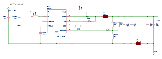
in my application i need a 5V/1,5A, a 15V/0,2A and a -15V/0,1A supply from 24VDC. As it is desireable to use the same ic for all 3 voltages, i decided the LM25011 would be a good choice. The buck configuration for +5V and +15V works perfect. However the ics used for buck-boost get killed immediately. I refered to http://www.ti.com/lit/an/slyt286/slyt286.pdf and ended up with the following schematic.

All capacitors are ceramic types, L18 is a ferrite bead. The frequency is close to 2MHz but the timing is well within constraints. A quite large inductor is used because of the small currents.

When powered the ic is getting very hot and afterwards impedances seem not to be very low but i can measure a diode voltage (vf) of 1,4V antiparallel to the catch diode (which i have changed with no effect). When i change the LM25011 it's gone until power is applied. I also unsed a 24V source with current limiting set to 100mA, but also the ics get killed immediately.

Anyone uses the LM25011 in buck-boost configuration? Any suggestions? Thank you very much.

Stefan

  • Hi Stefan,

    In Buck-Boost mode the abs max between the VIN and GND pin is (VIN+VOUT)=24+15=39V which is really close to the abs max 42V of the IC. It is possible to that there are spikes above 42V. The buck-boost circuit current flow is different than the buck current flow. Because of that the layout should be optimized to bring the GND connections (at th right end of inductor and the GND pin of CIN2) close together to minimze the loop area. This will suppress the ringing/swithcing spikes which is particularly important here becasue (VIN+VOUT) is close to abs max.

    You will probably also need to change the current limit to a higher value because the current flows in the output capacitor only during TOFF. So please set the current limit to (IOUT*(TON+TOFF)/TOFF. But this should not cause failures.

    I hope your circuit works well after these modifications. If not I suggest going to higher voltage devices such as LM25007, LM5008A, LM5006, or LM5017.

    Thanks and regards,

  • Hi Vijay,

    thanks for your help. Hopefully I will receive new samples of the LM25011 tomorrow. There is not very much I can do about optimizing the layout but i consider to use +15V instead of +24V on the input side to gain some more safety margin.

    Thanks also for the hint considering the current limiting resistor.

    Best regards,

    Stefan

  • Hi Vijay,

    finally i got it to work. I used the +15V of another LM25011 (which is in the Application anyway) instead of +24V. As there is only little power drawn from the -15V and efficiency is not that critical, it is appropriate here.

    Once again thank you very much, you saved my day!

    Best regards

    Stefan