This thread has been locked.

If you have a related question, please click the "Ask a related question" button in the top right corner. The newly created question will be automatically linked to this question.

LM2679-ADJ - current output limited

Other Parts Discussed in Thread: LM2679
Hi  
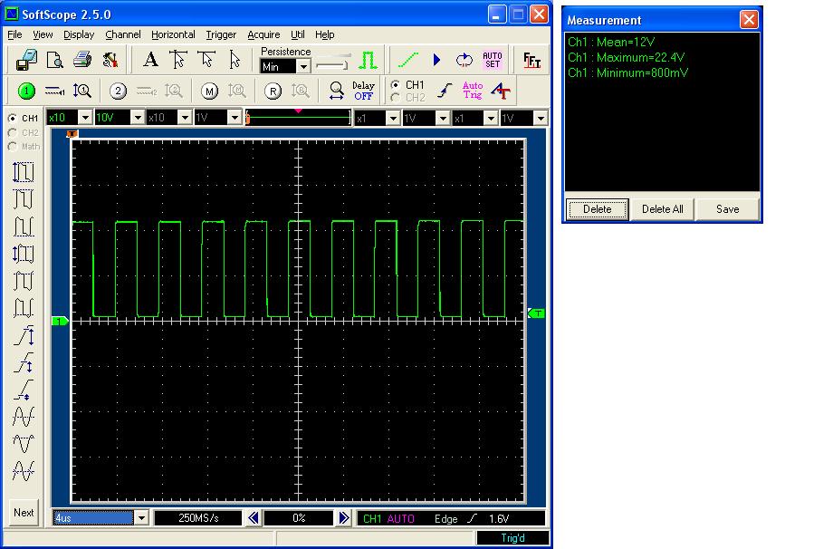
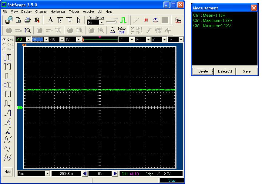
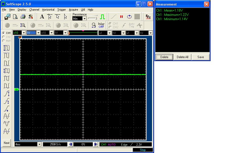
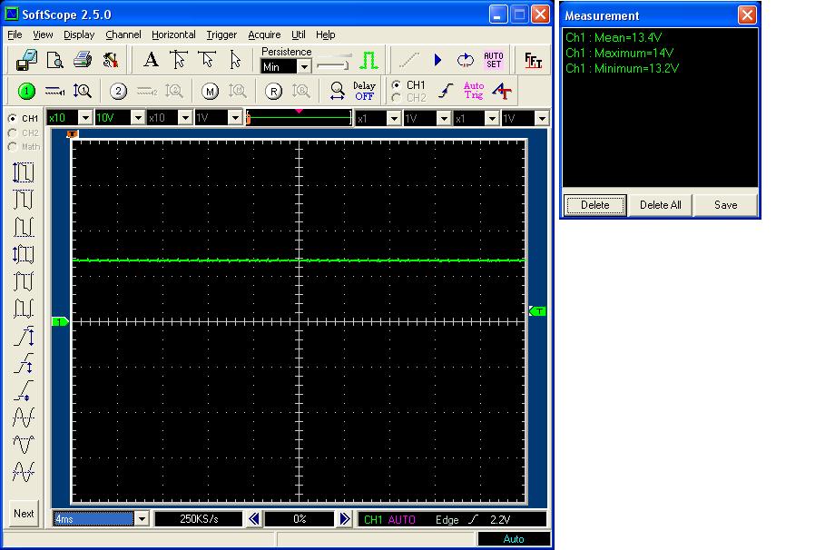
We are using LM2679-ADJ to generate a power supply for cooling fans. We are generating 3 voltage values - 8V, 12V and 13.8V by switching in appropriate programming resistor as need be. Load Current required is 2.8A. But for some reason we see that the load current is limited to 1.65 Amps and load voltage falls below the set value. I am using a current limit resistor of 8.2K OHM. Inductor,diode ratings are fine as per your datasheet. I also checked the switching frequency and it is around 260Khz which I guess is fine. 

Output capacitor used is EMVY350ADA680MF80G (3 Nos in parallel)
http://www.digikey.com/product-detail/en/EMVY350ADA680MF80G/565-2476-2-ND/757122

Since I identified the ripple rating of the above caps are bit less for my application I changed the caps to this - EEUFC2A121S
(2 Nos in parallel) http://www.digikey.com/product-detail/en/EEU-FC2A121SB/EEU-FC2A121SB-ND/2689798. This improved ouput current to 2.0Amps. 

There is a similar issue raised in forum earlier - http://wwwd.national.com/national/PowerMB.nsf/aac7d56ca8fd884b852563be00610639/95B5A855CD6C1F42882575AF0008C1E4?OpenDocument. But no clear answers here. Please help as am not sure what is causing the issue.  

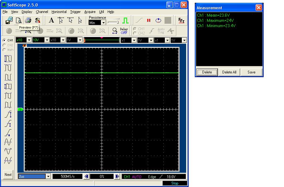
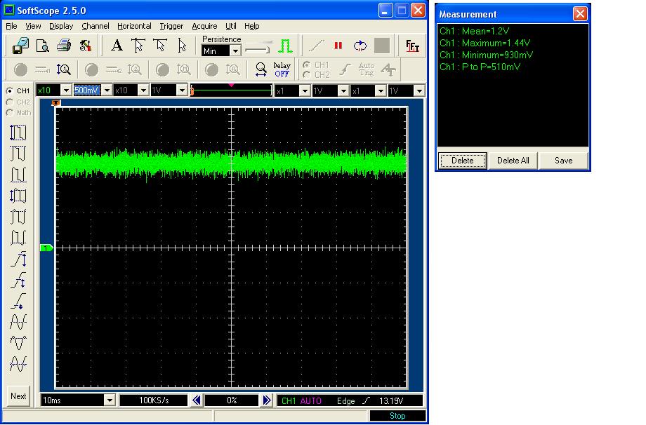
I think the capacitor ESR is causing the problem (I am seeing small oscillations at output when I connect the fan). I have placed order for lower ESR tantalum caps and will be testing the circuit in a weeks time. But till then any body has any idea what else could be the problem ? 
Best Regards 
Syam
  • Hi

    Another peculiar observation. The input voltage to the regulator is 24V. Current as said in the previous post is 2 A. But when I reduced the input voltage to about 18V regulator is giving desired 2.8A current. Cant figure out what is causing this. Please help.

    Best Regards

    Syam

  • Hi Syam,

    Can you please measure the voltage on the current adjust pin and compare to the voltage on the EC table. Also, can you try using 5.6KOhm instead of 8.2K just to isolate the problem.

    Can you share your waveforms (switch, Vin, Vout)?

    Regards,

    Ismail

  • I reduced the current limit resistor to 4.7K and tested the circuit. But still the issue remains. I have attached all the plots that you asked for below. As mentioned in my previous mail the current limit increases to the desired value (2.8A) if I reduce the input to about 16-18V. Any idea why this is happening ?

    Switch Pin Output

    Current Limit Pin Voltage

    Voltage Feedback Pin Voltage

    VOUT

    Voltage Input

    Best Regards

    Syam

  • Hi Syam,

    These waveforms are at the good condition when Iout is low. Can you send waveforms at the point when you start seeing unregulated voltage so we can evaluate the switch node.

    Also, What inductance are you using? from the E.T calculation you should be in the L40 range which is 33uH which corresponds to C5 or C6 (2x100uF) on surafce mount capacitor table for AVX or C7 (100uF) for through hole Sanyo OS-CON table. For panasonic HFQ table, it is 560uF.

    These caps chosen based on their ESR and Current ratings. If choose another cap, amke sure you match all the specs because the ESR zero is very critical for the stability of this part.

    Can you share your schematic and Layout?

    Regards,

    Ismail   

  • Thanks Ismail. The plots were taken with load connected (about 2A). Voltage doesnt vary at a level more than what was shown on the earlier plots.

    We are using a 47uH inductor (http://www.digikey.com/scripts/dksearch/dksus.dll?vendor=0&keywords=2100LL-470-H-RC).

    Initially like I said I was using this cap - EMVY350ADA680MF80G (3 Nos in parallel) http://www.digikey.com/product-detail/en/EMVY350ADA680MF80G/565-2476-2-ND/757122. But now am using this EEU-FC2A121SB (2 Nos in parallel) http://www.digikey.com/product-detail/en/EEU-FC2A121SB/EEU-FC2A121SB-ND/2689798

    Does this regulator have a minimum ESR limit ?

    I am attaching the relevant sections of schematic and PCB with this post. Note that we have four identical power circuits based on LM2679. We have 3 resistors on the feedback path with the intention of adjusting the output voltage from about 8V to 13.8V. Currently am testing with just one regulator enabled and with the feedback (1K) and current limit resistor (4.7K) soldered directly to the ground pin of LM2679. But still the problem is there. Please help.

    4113.SCH.pdf

    5074.PCB.pdf

    Best Regards

    Syam

  • Hi Ismail

    Yesterday when I took the plot the oscilloscope bandwidth limit was ON which restricted the bandwidth to 20MHz. I took a new plot of the signal at the current limit pin with bandwidth limit turned off. Please find that below. This is definitely more noisy than seen in the signal plot necessary. Currently am testing the circuit with only one regulator turned ON and with a 1K feedback resistor (about 13.4V output) and 4.7K current limit resistor soldered directly to the GND pin of the regulator to eliminate noise coupled from other regulator circuits. The noise pattern on the current limit pin is same even when the output current goes to 2.8A at reduced input voltages or with all regulators turned ON. So am not sure whether this noise is the problem. Any ideas ?


    Best Regards
    Syam

  • Hi Syam,

    I have reviewed your Layout and i believe it is the reason why you are not getting the full current at High Vin.

    I would suggest turnig the didoe 90 degree clock wise to have the grounds connected and fatten the small Vin trace using extra copper. Lift the inductor and solder it to the switch node on the diode, connect the other point to the top of the output cap.

    Regards,
    Ismail

  • Thanks Ismail. Actually VIN track has about good copper pour connected to it. See the attached PDF (Forgot to enable copper pour display while taking snapshot earlier). Today I also soldered the inductor directly to the Pin 6 of the chip and capacitor (other end of capacitor connected directly to Diode anode). So virtually all components are (Feedback resistors, diode, inductor and output cap) sitting very close to the regulator chip pins. But still the problem persist. Is there something else that can be done ?

    Best Regards

    Syam5824.PCB-COPPER.pdf

  • Hi Syam,

    I have tried to locate the Polygon pour on your new Doc and i could see it.

    I was refering to rotating the diode so that output ground will be connected to input ground on the input cap. Thats essential for the uck stability at higher load current.

    Regards
    Ismail

  • Thanks Ismail. I have already connected the power supply wire straight to the input cap pins which is infact soldered directly to the pins of the regulator. Diode was earlier connected to a ground plain and close to the regulator ground. But today I cut that grounding track and soldered the diode return directly to input cap return. Output cap return is also connected at this point. Still the issue remains.

    I don't see much ripple in the output since i replaced the original aluminum caps with lower ESR caps (type already shared with you). So I dont think regulator is unstable at higher currents. Its just that the current is getting limited somehow.

    I guess when the input voltage reduces the duty cycle of switching regulator increases + the gate drive varies. Other than this I don't think there is any other variation in the signals. Does any other parameter of the switching regulator change with variation in input voltage ?

  • Hi Ismail

    Can you please let me know the following things 

    1. Is there any minimum ESR limit for the output capacitor ?

    2. Will an increase in inductor value beyond what is given by the figure in the datasheet cause any likely issues ?

    3. Should we base the inductor max current rating on the peak switch current limit we are configuring or on the output current we require ?

    Best Regards

    Syam

  • Hi

    Today I changed the output cap to a tantalum cap (68 uf). So now I my test condtions are

    Input - 24V

    Output - 13.2V

    Inductor - 47uH

    Capacitor - 68uF tantalum (1 No)

    This is the behavior i saw.

    The current limit increased to 2.2A from 2A. But with the increased current we are seeing oscillations in the current drawn by the fan. When we first switch ON the supply the current ramps up to 2.2A, then stays there for a while and then a cycle of high current and low current consumption begins. First the current falls all the way back to 0.3A and then again ramps up to 2.2A and then from there falls back to 0.3A only to go up again.  I guess its the current limit circuit that getting triggered internally as described in the datasheet (page 12 - Additional Application Information). We have tried connecting the inductors in parallel (net value = 23.5uH, 10A) to beef up the current rating to prevent any inductor saturation that may be occurring, reduce the capacitor value to about 33-47uF (to prevent the current limit circuit from triggering as described in the datasheet) etc but the behavior described above is the best we could get till now.

    Some one please help.

    Best Regards

    Syam

  • Hi syam,

    To answer your questions:

    1- Based on the tables on the datasheet, you can use Ceramic or tantalum caps for outpout capacitance. This can tell us that ESR is not critical if you follow the suggested values. I would prefer using Tantalum with about 30 to 40mOhm of ESR.

    2- You should choose your inductor based on two parameters, DC current o be higher than Iout and Saturation current higher than Peak switch current. Make sure to leave a big margin.

    3- using a higher inductor value will give you more output current based on ripple but it sliglty shift your bandwidth to the right which could result into instability if you abouse it.

    I am still trying to build up your design.  

    Regards,
    Ismail


  • Forgot to mention, you have to use a bulk cap on the input about (150-330uF) alumunim. at 35V or 50V rating.

  • Thanks Ismail.

    I have added 240uF aluminum at the input. But still the problem persist. So now my test conditions are

    Input - 24V

    Output - 13.6V

    Inductor - 47uH

    Input Capacitor - 240uF aluminum

    Output Capacitor - 68uF tantalum

    Current Limit Resistor - 5.1K

    Voltage feedback resistors = 10K, 1K

    Were you able to build the configuration ? Also our load is a fan which is an inductive load. Can that affect the circuit stability in anyway with the circuit parameters above ?

    Best Regards

    Syam