This thread has been locked.

If you have a related question, please click the "Ask a related question" button in the top right corner. The newly created question will be automatically linked to this question.

tl783

I'm using the TL 783 to obatain 48VDC output for microphone Phantom powering. The input is a rectified (graetz bridge) 48VAC with two 470uF electrolitic capacitors. The resistors to obtain the desired output voltage are R2=2200 2W and R1=59 Ohm. In the output, near the IC there is a 470uF capacitor. Occasionaly at power up in the output, regardless of the load,  there is about 100-200mVAC at 100 Hz. This condition remain indefinitely. Switching off the power line and powering it up again the regulator usally work fine. In the datasheet is used an R1=82 Ohm. Is it R1 too low? Thank you in advance for any help

  • In general, the value for R1 to ensure the 15mA output current requirement is always met is:

      R1 ≤  Reference voltage / Minimum output current to maintain regulation

      R1 ≤  1.27V / 15mA    (Note: EC table says typical Vref is 1.27V, while 'Design Considerations' text says 1.25V)

      R1 ≤  84.7 Ohms

    Using 59.Ohms and 2200.Ohms will give an appropriate output voltage (~47.3V).

    Using a lower value for R1, especially with higher output voltages, may require the use of higher wattage resistor for R2.

    Alternately, higher values for R1 and R2 may be used if a third resistor is in parallel with R1 and R2, or a load is always present, to ensure that there is always a total of at least 15mA of output current. Higher values for R1 and R2 will cause the error value from the ADJ pin current to be increased proportionately.

    Since your problem is seen at start-up (power on) only, and is not dependent on external load, it may be that the output capacitor value (470uF) may be affecting the start-up. I will suggest 2 points to try: 1) add a protective diode (See "Figure 15. Regulator With Protective Diode" in the data-sheet); 2) reduce the output capacitance value to see if there is any improvement..

    You did not mention your load current requirements, or provide a schematic, so my response is limited.

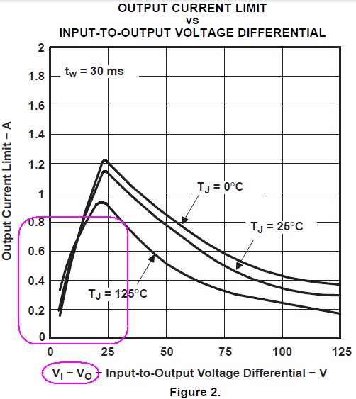
  • Thank you Donald for your answer. There's already a protection Diode as data sheet suggest. Today I made some new tests and I've seen that the spurious output is a saw tooth 400-500 mVpp and with a frequency load dependent in the range of some undred of kilohertz. I tried to reduce the output capacitance and it helped to reduce the times the issue arise. With a 47uF and a dummy load of 2.2 kOhm (Vo=48V) it seems never oscillate at start up. With no load the saw tooth appears very often at start up. With two caps of 47uf in parallel the situation get worst. If the load is connected after start up the problem come back again. It seems a problem related with the current limiting circuit of the IC, in fact if I cc the output during power on the oscillation starts. My current requirement is less than 200mA but the presence of the load is variable. I can use a dummy load to reduce the problem but seems that I need to limit the output current charging Co or farther reduce its capacitance but I'm not sure that the problem is solved at all. What do you think about.

  •  

    200mA load current, by itself, should not a problem.

    I would check input voltage, with minimum and maximum loads,  to make sure input is behaving as expected, and that you always have enough head-room for proper operation. I would recommend at least 10V of head-room (i.e. Vin=58V @ Iout=200mA).

    Do you have accurate schematic you could share?