This thread has been locked.

If you have a related question, please click the "Ask a related question" button in the top right corner. The newly created question will be automatically linked to this question.

Exiting from excessive load (or short circuit) condition in TPS61087

Other Parts Discussed in Thread: TPS61087

Hello, I have a problem in step-up circuit based on TPS61087.

The situation is the following :

The step-up is powered from a Li-Ion battery at 3.6 Volt (up to 4.2V if fully charged) and the output is set at 12V.

When I put a load (heavy load) on the output, the circuit stops oscillating, and the battery voltage drops to very low value ;  that's OK, I understand there is an overload and it's normal that my battery goes undervoltage, but... if I remove the load, the circuit still remains in the same condition and same does the battery. It looks like the output mosfet of TPS61087 is shorted and the battery sees the inductor as static load to GND.

I tested the same situation, with identical results, on the demo board purchased from TI and the behaviour is the same, so I don' attach my schematic that's directly derived from the app-note.

Note that if I connect the whole circuit (battery included) to a Li-Ion battery charger, even with limited charge current of 100mA, the step-up restarts when I remove the load.

Any suggestion will be highly appreciated, thanks !

  • Please make sure your battery is fully charged or change a new one!

    You can also try it with DC power supply, I am afraid you just had a bad battery.

    If this till happens,please check the SW pin voltage to see if the chip is swiching correctly.(Maybe you can catch some waveforms to show)

    Regards

    Jim Chen

  • Hello, thank you for the prompt answer :)

    Yes, the battery may be a little bit discharged, but the problem is that if you go under 2.4 Volt (that's the limit of the undervoltage lockout), the step-up is disabled, but the mosfet is conducting and, that way, the battery that was partially discharged becomes quickly fully discharged (and again overloaded).

    In the situation described, I have only one method to restore the system : physically disconnect the battery, then connecting again.

    This is a problem for end-user that probably doesn't want to disconnect the battery from inside the box.

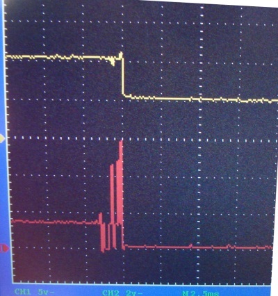
    In the attachment I supplied the oscilloscope dump of the battery voltage (the yellow line) and the SW pin of the chip, triggered with a short circuit on the output of the step-up. As you can see, the mosfet output is shorted to gnd. The condition persists if I remove the short circuit, in my opinion 'cause the undervoltage lockout takes place due to low battery level.

    I think that a mosfet-open condition in case of undervoltage is more appropriate, so the eventually partially discharged battery will not be stressed by a short circuit thru the inductor and internal mosfet.

    Can you try the same experiment on your demo board and eventually give me a solution for a battery powered step-up (with possible short circuit behaviour) ?

  • TPS61087 uses external diode as the rectify diode.So if vout is shorted to groud,there will always be a path throug battery-inductor-external diode-ground.

    What's the load in your application?Is it series  LED?

    The waveforms is a little strange to me.At  the beginning Vin is 10,but there's no switching at the SW pin,SW voltage is ca1.8V.It seems the boost is not working.

    There's some switching before the short circuit happen, but the switching voltage is also not that right, between 4V to 6V.Do you know what's happened here?

    After the short circuit happen,switching stops again with battery voltage above 5V.The boost seems not working.

  • Hello, thank you for the answer.

    Sorry for the picture, may be isn't so clear. Please, note that the yellow and red arrows at the left of the screen are the ZERO volt level for each track and also note that the RED signal (the step-up output) is 5V per division, while the yellow line (the battery input) is 2V per division ; reading the screenshot with such infos, you can see that the step-up works at 15Volts out, while the battery input is at 4 Volts. When I apply a very fast short circuit, the battery level goes down to 2V and the oscillator stops with mosfet in full conduction. I say the mosfet is short circuited, 'cause it REMAINS short circuited even when I remove the heavy load. So, the rectifier diode isn't involved in the battery discharging path. I tested it on my design circuit and on your demo board, and the behaviour is absolutely the same. I can restore a working condition only disconnecting -then reconnecting- the battery. This is a big problem for my application. Hope you can test this situation on your demo board and also hope there will be some workaround to make my circuit perfectly working. Thank you.

  • Yes,I can do the test on the EVM.But currently I have no EVM board on hand.I have applied one on the TI website.But it will take some days before I get them. 

    The waveforms looks more reasonable with your description now.Thank you!

    From the waveforms we can see there's no switching at the begining.SW voltage remains 4V.After some time, it switches. SW voltage goes up to 15V in ca 1.5ms.

    So I suppose that you didn't enable the device at the beginning.The device is enabled at 6ms if we assume the very left side of the waveform window to be 0ms.Am I right?

    After you add the heavy load,SW drops down to 0.3V?(SW voltage seems not to be 0V to me.)After you add the heavy load, could you please help to check the current value into the inductor and the rectifier diode ?(just by lift the inductor and rectifier diode up, and solder a short wire in series with them,then test the current).From the current information we can see if there's a short circuit from SW to gnd through internal NMOS FET or through rectifier diode .