This thread has been locked.

If you have a related question, please click the "Ask a related question" button in the top right corner. The newly created question will be automatically linked to this question.

TPS40041 Issue with CSD87331Q3D

Other Parts Discussed in Thread: TMS320DM8168, TPS40041, CSD87331Q3D, TPS40040

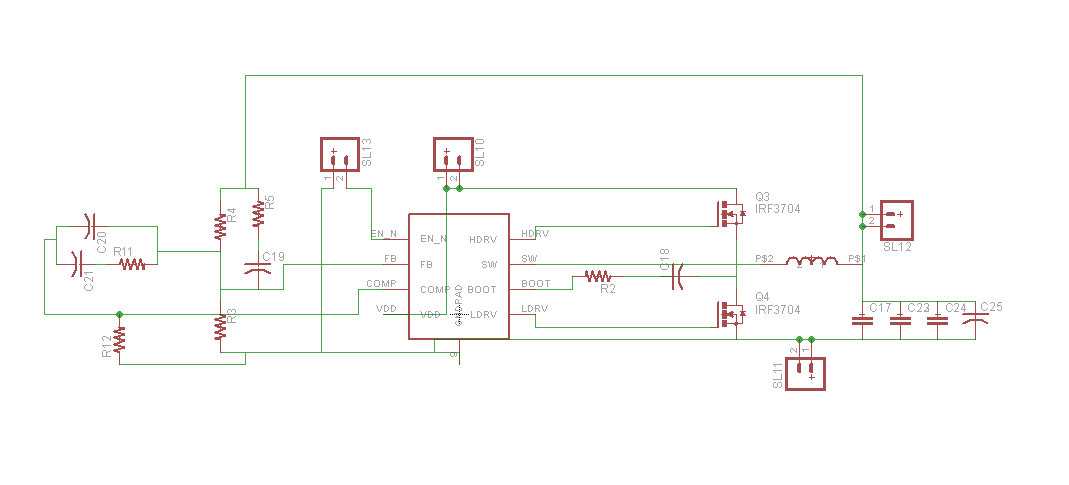
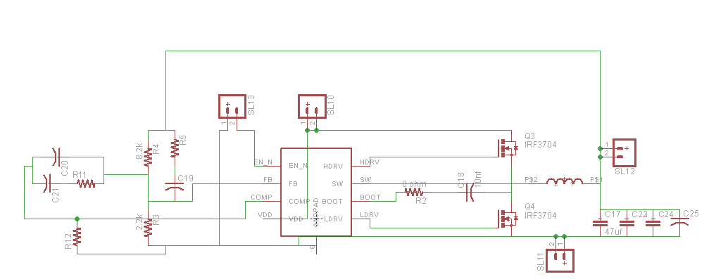
Last May i've designed with SwitcherPro a project for the 1-V  AVS (adaptive voltage scaling) CVDD required from the Da Vinci Soc TMS320DM8168, I attached the schematic below:

3678.SwitcherProTPS40041.PDF

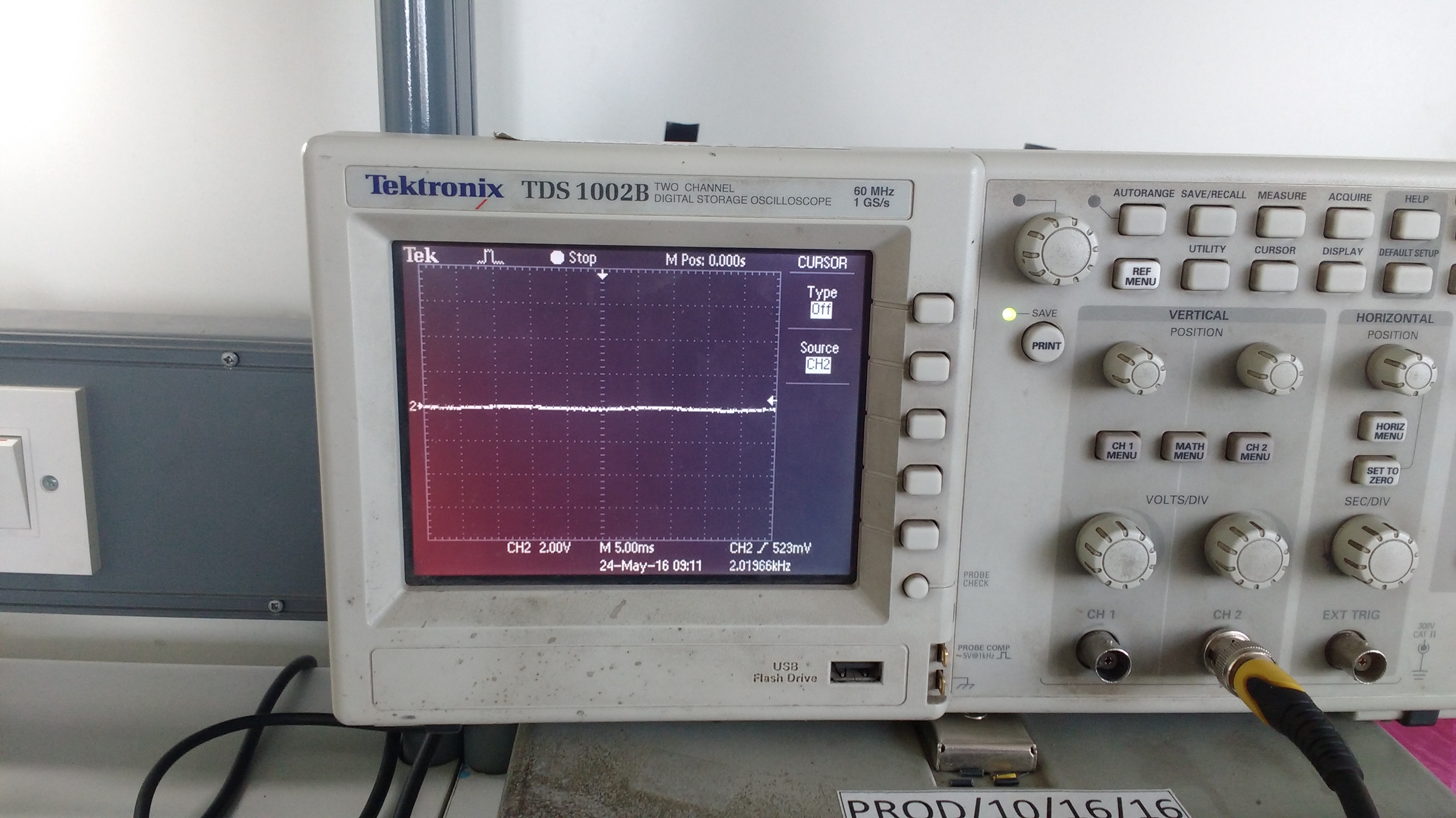
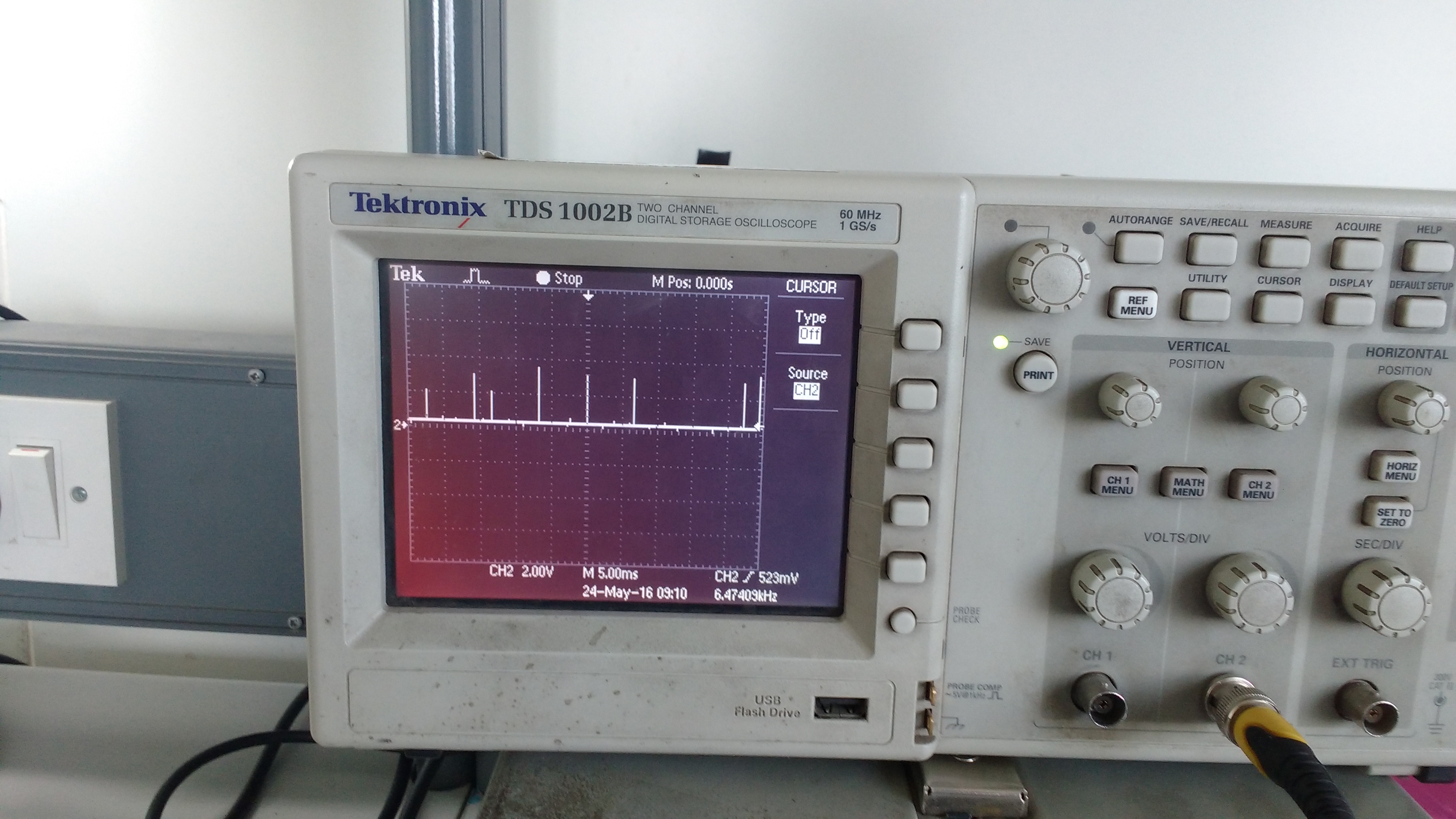
The board doesn't work correctly because the TPS40041 turns off (we think that go in Short Circuit Protection?) 1 to 8 times before run correctly as you can see on the acquisition below of COMP pin:

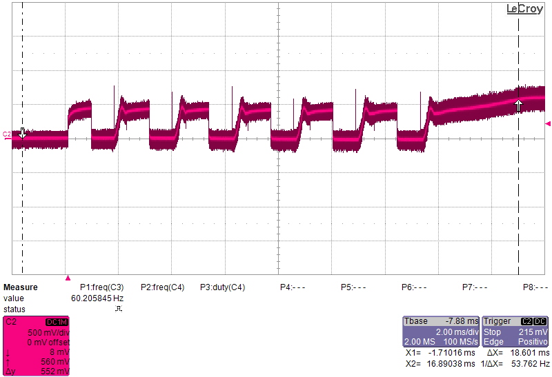
The waveform is similar to the EVM but there are 5 more cycle before the start up.

I follow some suggestion find in other post:
- Changing the COMP R-C-network.
- Increasing the input and output capacitor
- Adding a 2,7 Ohm bootstrap capacitor series resistor.
- Testing the different Short Circuit Current Limit Thresholds using a resistor at the COMP pin.
- We also changed boot capacitor value to 22nF (C7) due to low gate charge of the CSD87331Q3D.
But doesen't solve the problem.

Is there some problem with CSD87331Q3D?
How can i solve?

Thank you.

Regards,

Emanuele

  • Hi Emanuele,

    From the COMP waveform, I don't think the shut-off is caused by the short-circuit protection. Because if that is the reason, the fault time-out is 7 soft-start time, i.e. 28ms typical. During the time-out, there should be no activity on COMP.

    I would suggest examine the waveform on VDD and EN bar pins. What is connected on EN bar pin? To have the part startup, the EN bar pin should not be left floating.

    Regards,

    Na

  • Hello Na,

       I am also having similar kind of problem with TPS40041 that COMP pin is showing rectangular pulse wave continuously which has frequency 450Hz and amplitude around 350mV. Gate drive waveform seen indicates that MOSFET are not getting switched at all. LDRV is always zero while HDRV is high for very very short pulse width. I think this indicates that IC remains always in calibration mode.

    Can you please help me why this problem is arising in my circuit of step down converter?

  • Hi Adesh,

    I'm supporting TPS40040 and TPS40041 now.

    Can you provide the schematic and test waveform (EN, COMP, HDRV, LDRV)?

    Thanks

    Qian

  • Yes. I am attaching photos of graphs here. Please follow the attachment

    EN graph:

    COMP:

    LDRV:

    HDRV:

    schematic:

  • Hello,

      I observed one strange thing as well. COMP pin is not the same as I attached in previous mail when VDD lies between 3.0V to 3.6V. at VDD=3.5V, COMP pin is observed at 1V. After 3.6V that problem of COMP pin showing square wave is observed and output of buck converter is zero.

  • HI Adesh,

    Thanks for the waveform. Can you provide the real schematic with all components values?
    No Vin cap?

    Thanks
    Qian
  • Please do refer above schematic. I have not use compensation circuit there on my board that is why I didnt show values of component in compensation circuit. And about VIN cap, I did not use it because  I am using regulated power supply. So I think it won't make any difference. without VIN cap and compensation network circuit should have work at least on no load condition right? value of inductor is 6.8uH.

  • No, the compensation must be used to make the circuit work correctly.
    A bypass cap must be placed close to VDD pin.
    Please refer to reference design on datasheet and EVM user guide.

    Thanks
    Qian