This thread has been locked.

If you have a related question, please click the "Ask a related question" button in the top right corner. The newly created question will be automatically linked to this question.

Output problem of TPS78601

Hi,


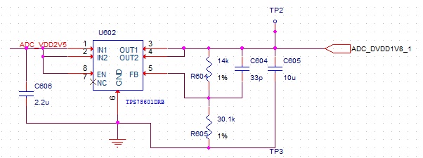
I am using TPS78601DRB to power two LTC2158 ADC. The input is 2.5V and output is 1.8V.

The output is connected to the ADC through ferrite beads. When the ferrite beads are on, the output is 1.71V, and the voltage of FB pin is about 1.17V, not 1.2246V as in the datasheet. When the beads are removed, the output is zero.

I use the right E96 14k and 30.1k resisters right as told in the datasheet.

I have two modules with the same problem, except the output is not 1.71, but definitely not 1.8V.

What might be the problem?

Thanks

Chao Xiang 

  • This is the schematic, which is the same as that in the datasheet.

  • Hi Xiang,

    It might be good to look at input and output voltage waveforms during startup with and without ferrite beads. It may be that the IC is getting damaged. It will also be good to test this without the ADC load connected first as it might be the load thats dropping the voltage.

    Regards,

    Darwin

  • Hi Darwin,


    I checked the input and output of it. They looked just as normal DC with some ripple.

    But the output is 1.71V instead of 1.8V.

    Is that the problem of the chip? I doubt it is damaged.

    The follows is the mark on the chip.


    Is this the right chip?

    There is no model number on it, and I can't find what those marks mean in the datasheet.

    Chao Xiang

  • Hi Xiang,

    Searching the part marking below yields the TPS78601. Have you tried removing the load to verify if it is not the load?

    http://www.ti.com/general/docs/partmarking/partmarkinglookup.tsp?startPosition=0&navigationId=0&templateId=0&siteFlag=0&keyword=oci&searchType=partmark

  • Hi,


    It looks like this is the right chip.


    After remove the ADC load, the output is still 1.7V. I assume that the chip is of problem.

    And maybe I should replace it with a new one.


    Hope it will work.


    Chao Xiang

  • I am totally confused.

    I have removed everything from the output (including the capacitors), and replaced the chip, but the problem remains.

    One TPS78601 output is 1.77V and the other is 0V.

    What other cause may it be? The schematic is OK?

    I can't figure out anything.

    Thanks

    Chao Xiang

  • Hi Xiang,

    I apologize I did not catch this sooner. The minimum input voltage of the TPS78601 is 2.7V. You must increase your input voltage from 2.5V to at least 2.7V to properly bias the internal circuitry of the LDO.

    Please let us know if this helps.

    Regards,

    Darwin

  •  Hello Darwin.

    I'm facing  a similar problem.

    Due to a misunderstanding I'm using TPS78601-Adj to generate 1.9V through external feedback resistors (30k, 16.5k), but using by mistake 2.5V Input supply. The (now) obvious results is that the output is something like 1.8V in place of 1.9V expected.

    I can't change the PCB so I have two solutions: solution 1 is to try to cope with this error,  solution 2 is to add a wire somewhere (to be avoided if possible).

    I've calculated that probably the lower output is due to  the internal reference actual value that is in the range of 1.16V instead of 1.2246V, and Xiang Chao above measurement 1.17V confirm this. 

    So I guess if use this actual value for internal reference I can calculate new feedback resistor corrected values (26.1k, 16.5k) that allows to reach 1.9V output.

     I see from datasheet that UVLO threshold range variation is 2.25 to 2.65V and this is probably why the minimum input power is 2.7V. 

    Considering that I'm using the device at <1A (50% margin on output current)  and that the devices I'm using, luckily, have  low UVLO so that they are not blocked by 2.5V input voltage, is there any reliability issue in using the devices, the way I described above with corrected resistor values?  I may tolerate some penalty in load regulation (if any). 

    Please explain your answers since IMHO there can't be any reliability issue at lower voltage and lower current than typical values, provided that we are so lucky to have devices with low UVLO threshold and thus the ICis working even at 2.5V input.

    Thanks in advance for any of your answers.

    PS: I know that the error is on my side, but since I've seen I'm not the only one to misunderstand input voltage specs,  I would suggest TI to put more in evidence in the 1st data-sheet page that the input cannot be lower than 2.7V, while there you may find  1.3V minimum output and 0.39V dropout with no mention to the Input voltage to be larger than 2.7V anyway. To find such limitation (which to me is very odd and makes this component quite different from other customers LDO with simlar output range) we have to go to page 4 and read Note 1.......

  • Hi Gianluca,

    Thank you for your feedback. We will be sure to consider your comments to make the input voltage range more clear for the customer. Since your application does not violate the abs max ratings of the device, I do not foresee reliability issues. However, since it is being operated out of spec, device performance cannot be guaranteed. You may need switch to a different IC that meets your input voltage requirements such as the TPS7A4501.

    Regards,

    Darwin 

  •  

    Darwin,

    thanks for your kind reply.

    The problem I'm facing is that I'm using the DFN 3x3mm 8 leads (DRB package) and I would like not to re manufacture the PCB. 

    Is there any  part number  DRB footprint pin to pin compatible to TPS78601  (even de-rating to 1A output max current)?

    Being now assuered that there would be no reliability issue  in using TPS78601 @2.5V Vin  with corrected resistor values (see my previous email) and provided that it turns on, regarding performance degradation,   what do you expect to be the more affected parameters (i.e. load regulation, noise etc)? Is there available any measurements?

    I know system are not linear, but since 2.5V is out of spec by only 7.5% w.r.t 2.7V may I assume performance degradation would be not too high (say 15% as rule of thumb)? 


    Ciao.

    Luca


  • Hi Luca,

    Unfortunately, we do not have a p-p alternative with a lower input voltage range and there is no way of knowing the performance degradation when operating below the recommended operation conditions since we do not characterize this.

     Without changing the PCB another solution is increasing the input voltage. What is driving the input? Is it possible to increase the input voltage?

    Regards,

    Darwin

  • Darwin,

    the only way I can feed the TPS78601 with a larger Vin is using one  2 cm  wire to sink current from an available 3.3V source not too far on the pcb. This would probably work but I would try to avoid it for other reasons.

    I'm already succesfully using the board with 2.5V Vin to TPS78601 used to generate 1.9V for an ADC. Actually ADC performances are satisfactory to our needs so my original question was related to reliability issues supposing I continue to under-feed the regulator. 

    So the real question is :

    - since the TPS78601 it is not affected by reliability issues working at 2.5V Vin;

    - since measured performances on circuitries are anyway satisfactory;

    do you think we can continue using it in this way or are we obliged to find an the wired rework?

    Thanks.

    Luca

  • Hi Luca,

    I highly recommend using a different device that meets the input operating conditions of your application. This way, you will have optimum and characterized performance.

    Regards,

    Darwin