This thread has been locked.

If you have a related question, please click the "Ask a related question" button in the top right corner. The newly created question will be automatically linked to this question.

LM20333 oscillator sync

Other Parts Discussed in Thread: LM20333

I have a question regarding synchronization of the LM20333 to an external clock source. I believe that I have a design that essentially works but there is jitter in the switch node waveform with respect to my external clock source. The circuit moves through its range of duty cycle cleanly and doesn't oscillate. It works both at the free-run frequency of 200kHz and at the sync source's frequency of 600kHz. Finally, it does not oscillate at light load, no load, or max load.

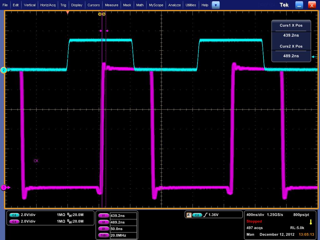
I'm attaching an oscilloscope picture that shows the clock source in blue and the switch node waveform in red. The persistence is all the way up so that the range of the jitter can be seen. It's about 50ns pp. 

The circuit is set up as follows:

12V in (nominal)

4.3V out @ 3A max (1.25A load in picture)

L = 10uH

C out = 2 x 100uF X5R ceramic

C comp = 5600p

R comp = 15k

C across R comp and C comp = 47p

 I have noticed that if I sweep through a range of clock frequencies by hand I can find some for which the jitter increases and others for which it reduces to practically zero ( 1.2MHz). It seems like it has to be related to the PLL in the device. Is this normal behavior?

Thanks,

Tom Strait

  • Hi Tom,

    You shouldn't see jitter of that magnitude.  It looks like your compensation should be fine with plenty of phase margin, so that isn't the problem.  If stability isn't the problem, then the jitter is usually a result of noise that will coincide with the time at which the switcher comparator makes the decision to shut off the HS and turn on the LS.  Usually for this device when we see jitter, my first response is to be sure you have the cap. directly from COMP to GND populated with at least 22 pF, as it will help high frequency filtering on the COMP node.  It sounds like you have a 47 pF so that should be OK, but it may be worth trying a 100 pF. Other potential noise possibilities are excessive input noise (how much input capacitance do you have?), very high sync. pin edge rates (does changing the SYNC amplitude influence the signal at all?), and layout problems. 

    If you could try the parallel cap. from COMP to GND change from 47 pF to 100 pF and let me know if that makes any significant difference, then I can make some further suggestions if it doesn't work.

    Hope this helps,

    Mike

  • Mike,

    Thanks for responding so quickly. I increased the parallel cap from 47pF to 100pF but it didn't appear to change it at all. The circuit is essentially what is on the LM20333 evaluation board (page 5 of AN-1791).  I have the same input capacitors. Each one of the two 4.7uF caps is close to the Vin and GND pins on either side of the device. The guy who did the layout copied the parts placement of the layout of the evaluation board from AN-1791. There are probably some subtle differences in the layout but it looks like it's substantially the same. The sensitive things don't look to me like they're glaringly wrong.

    Also, it looks like it doesn't have anything to do with the edges of the sync signal being too fast. I switched the function generator from square to sine out of curiosity and it happened to behave exactly the same at 600kHz. Similarly the amplitude of the sync signal didn't seem to affect it. 

    Any other ideas?

    Thanks,

    Tom

  • Tom,

    I'm not exactly sure where to look next.  I have two questions 1) what is the inductor part number and 2) where does the worst case jitter occur?  I can go to my bench and see if I get similar results.

    Regards,

    Mike

  • Mike,

    The inductor is a Vishay IHLP2020CZER100M01 (Digikey 541-1272-1-ND). I had a Cooper DR124-100 in there at one point while trying to sort out other issues. I should try it again to see if the behavior is any different. 

    I looked at a few different frequencies. It looks like it gets progressively worse as I go from 900kHz to 400kHz in 100kHz steps. It may be 20ns to 30ns pp at 900kHz vs 60ns to 70ns pp at 400kHz. Also, I noticed that it loses lock at about 1.12MHz. Then as I increase the frequency it will lock again on 1.18MHz with zero jitter. It is then locked to the clock with no jitter until 1.21MHz. The only frequencies where I can observe no jitter are in the band from 1.18MHz to 1.21MHz. The behavior is the same whether loaded at 1.25A or no load.

    Thanks,

    Tom

  • Tom,

    Unfortunately I came down with something today and the way its looking I won't be in until next Monday.  I'll test this out and get my results to you then.

    Regards,
    Mike

  • Mike,

    OK, sorry to hear that. I've played around with it today. No breakthroughs. It don't think it's a show-stopper but it would be nice to know why it acts the way it does. I wanted to mention too that our board that contains this power supply has two of these switchers on it. One is set up for 4.3V out and the other is set up for 3.0V out. My test board is populated with only the switchers and the behavior of both circuits is the same.

    Thanks,

    Tom 

  • Tom,

    My memory with this device has failed me - I see about the same results on an EVM board with a totally different configuration.  Jitter gets worse at lower frequencies, around 60 ns at 300 kHz, and improves to 20-30 ns at 1 MHz.  Hopefully this jitter is tolerable in your system, I no longer believe that it can be eliminated.  I can verify though that it definitely is not due to instability, it is just inherent noise.

    I don't know why it disappears for you at 1.2 MHz - you may be hitting the min. on-time.  Is it a fixed pulse width when this occurs, or any pulse skipping?

    Regards,

    MIke


  • Mike,

    OK, that's good to know. I think it should be fine in our system. Also, when the jitter reduces to zero at around 1.2MHz, the pulse width is fixed and there is no pulse skipping. It's the same with a 1.25A load or with no load.

    Thanks again,

    Tom