This thread has been locked.

If you have a related question, please click the "Ask a related question" button in the top right corner. The newly created question will be automatically linked to this question.

Setting up Advanced bqMTester

Other Parts Discussed in Thread: BQMTESTER, BQEVSW, BQ20Z80, BQ20Z65, BQ20Z65-R1, BQ24765

I have the HPA495 bqMTester and no matter what I do I cannot get the Station Setup executable to see the board.

It says:

"Board 0 was either disconnected or is in use by another program. Please make the corrections and try again"

followed by;

"Communication error -1 trying to read board firmware version"

then;

"Communication error 2 trying to read ID for board number 0"

I'm using software version 2.0.0. I've uninstalled, reinstalled, rebooted and redone the drivers several times to no avail, same thing happens all the time. Any ideas?

  • We will need more information to help. to begin with

    1. Which operating system is this running on?

    2. Is the machine a laptop or a desktop?

    3. Does bqEvaluation software detect the EV2300 and the firmware on the same machine?

    Regards,

  • Windows XP Pro SP3

    Desktop

    Yes I can detect the EV2300 and talk to the Gas Gauge using the bqEVSW

  • Just tried with the same software and it successfully detected the stations based on EV2300 detection(shows cal board not found). I did not have anything connected to the EV2300.

    Can you connect just the EV2300s to the desktop without any SMB/I2C connections and see if Station Setup can detect it?

  • I get the same responses with just the EV2300 connected. Also for what it's worth when it prompts me for a password it only accepts no password, if I enter bq20z80 it tells me there is an incorrect password.

  • Yes, it accepted only no password, i believe the documentation is out of sync. The older versions had the "bq20z80" password.

    The error messages shown indicate that the EV2300 is not connected. (Error code 2 is no USB). Since bqEvaluation software detects it and it uses the same components to communicate with the EV2300, it does not make sense why the error would be shown. Initially i suspected a bug in the software but after installing the bqMTester software everything is working for me.

    The other reason i could think of as to why the EV2300 is not connected is if it gets overloaded and resets. The Vout pin is used to flash the LED and some hardware specification may have been violated on either side. But disconnecting the target from the EV2300 disproved that theory.

    All other things like administrator access, permissions etc would apply to bq Evaluation software as well

    The Single station tester is also installed alongwith bqMTester. If i open it without any EV2300 connected it gives me an error "No EV2300 found! Please close the app."

    I'm curious whether it does the same on your system while the EV2300 is connected.

  • If I open the single station tester with no EV2300 I get the same response as above, however if I plug in my EV2300 the program opens fine with no warnings and I can change all the settings and stuff, the start button is grey the entire time though. It seems as though the EV2300 is connecting I just don't know what's up with the bqMTester software, I get those same errors no matter what is connected or disconnected.

  • Interestingly if I run the Station Setup software twice once with nothing connected, I get no error and all of the station locations say "Not Found", if I run it again with EV2300 plugged in it throws the errors and now the first station is populated with "..." whilst the remainder say "Not Found", so it seems to be seeing it but it just can't communicate. I'm going to try it on another machine and see if I can get it to work.

  • That is a good sign. Its puzzling why only bqMTester is not recognizing it.

    The start button on single station is enabled after

    1. global configuration is set

    2. VTI is configured.

    3. Settings are locked

  • That is typical of a USB cable problem but its working with bq Evaluation software and Single station Tester.

  • I am attaching a recent version of bqMTester in case you want to try.

    0511.TIbqMultiStationNB2.27Setup.exe.zip

    http://e2e.ti.com/cfs-file.ashx/__key/communityserver-discussions-components-files/180/0511.TIbqMultiStationNB2.27Setup.exe.zip


  • The advanced bqMTester works better, it's still really finicky and involves frequent rebooting and disconnecting and reconnecting. I loaded it onto a different machine (Windows 7 64-bit) because I could not get it to work on the older XP machine, my guess is there was a previous install there that I couldn't get rid of even by uninstalling and reinstalling.

  • Can you send the error message that makes you believe that there is a previous install?

    Thanks

  • The errors detailed in this thread are the only errors I've seen. The machine can't talk to the device and I know I've previously installed the old version and then uninstalled it so that's what makes me think that might be the problem. It doesn't really matter now I don't have time to debug it and I've found a way to talk it. Now I have to spend unnecessary amounts of time addressing the next silly problem. Error Code 65570, according to sluu397a  "Sense resistor value too high in post cal checks"

  • Pat

    We may have gone overboard with the checks and balances required to ensure that the gas gauge is configured correctly at the end of the procedure to the point that any small problem results in a fail status. But most of the requests to add these checks came from customers like you.

    I can help you with the 65570 error. The design objective of this error is to flag boards that have poor soldering connections or incorrect sense resistors used. Essentially it is looking for the ideal value(usually 10mOhm, but is different for some devices) and then a tolerance around this value. If you are consistently seeing this error then it indicates that something is causing a high or low value. It does not affect gauge accuracy unless it is off by a factor of 2. You can disable this error by updating global configuration. Either set the Sense resistor value to match the actual or calibrated value or increase the %Error acceptable.

    Related to the USB disconnection and communication error, we had the opportunity to see one system that did the same. After debug it turned out that the internal USB hub was not able to power the EV2300, it was only supplying 120mA max. EV2300 is designed for 500mA USB supply which is standard USB. The problem went away when we powered the EV2300 externally. Of course you could be having an entirely different issue.

    I hope this information is useful and saves you some time.

    Regards

  • The value used is 10mOhm so I'm not sure why it's throwing the error, I can get it to pass by setting the tolerance to 100% but that hardly seems ideal. At any rate after it passes that it fails on the next test, 65590 "Temperature value too high in post cal checks".

    My ultimate goal here is to generate a golden image for our pack but before I can get to that I have to calibrate the board and I'm getting stuck on these post cal checks, although I'm slowly making headway. I'm not entirely sure how the board can possibly fail these checks immediately after being calibrated unless the calibration isn't sticking in the part?

    It's plausible that the problem you mentioned is the problem I was seeing with the other machine, I'd be surprised as I'd expect windows to tell me it was shutting off the hub.

  • Pat

    You can use bqEVSW to calibrate and check what the value of Gain is under Calibration tab of Data flash. This is the value that is compared with the global configuration. With strict quality control a 25% tolerance is reasonable. For bench assembled devices i have observed upto 50% variance personally. A large sample of devices is really required to say if it is a consistent problem or one off board issue.

    Temperature and board offset tolerances can be very high. We usually set 5deg (50)  for temperature offset. Board offset depends on a lot of factors and can vary based on PCB design, so if you run into that, you can just increase it.

    One of the challenges in production is that one mistake is multiplied by the number of boards it is used on. Rule of thumb is to go with default values, then run on a large sample and then tweak the values as we gather more and more data. In all cases refer to the calibration data in data flash after bqMTester finishes calibration to cross check if calibration values seem to be proper. Also verify current and voltage, accuracy in measured values means that calibration completed successfully even if the compensation(tolerance) values are high. If we knew with certainty how much tolerance to expect in hardware then we probably can get rid of calibration step altogether and quantify the possible increase in error as part of datasheet.

    You mention that you are trying to create the golden image for the pack. This is done using bqEVSW.

    Set DF(dataflash), calibrate, run optimization cycle  (all using bqEVSW ) and then read out .rom file using bqTesterDFReader(part of bqMTester installation). The multistation tester board setup comes after this step. So i am a little confused by the comment.

    My posts are getting a bit long. Please let me know if you have any questions.

  • Yes bqEVSW software has the calibration step also but I figured if I I could do this calibration step with the bqMTester I wouldn't have to redo it in bqEVSW and I wouldn't have to worry about accuracy issues in my supplies?

  • Thanks for the clarification.

    bqMTester is really not designed for single board evaluation use, the settings are expected to be tweaked multiple times with statistical data before it is finally used.

    Another rare possibility is defective hardware. What are the values of Voltage, current and Temperature measured/entered in VTI configuration?

    bqEVSW is designed for evaluation but as you said it requires accurate supplies.

  • The values entered into the VTI (and measured from the reference headers) are 14734V, 1994mA, 21.5C

    Do you think it is inappropriate to use the bqMTester to calibrate the board?

  • The VTI values are in range. It is unusual to use bqMTester before having a golden image but it should work.

  • I chose instead to do the calibration with bench supplies, I had spent too long playing with the bqMTester. Calibration seemed to go ok, I loaded the dataflash we have setup for this part, chose the correct chemistry file and I'm ready to begin the test cycles.

    1) I noticed that QEN is set even though I don't believe I have explicitly enabled the Impedance Track yet.

    2) Is there any reason why the unit has to communicate with BQEasy for the entire cycle (or at any time in the cycle after IT is enabled)?

    3) In the event of a failed learning cycle is there any way to clear what the IT has learned and start from fresh, can it just relearn over what it has or do I need to populate a new part?

  • Pat,

    1. Is it possible that the command for IT enable was sent at some time after the part was received? The learning cycle requires a significant charge/discharge, so even if QEN is set it will not have learnt anything without a charge/discharge. You would need to set chemistry before doing the learning cycle

    2. I did not understand this question completely.

    3. There may be an app not for how to start over. I will let someone from the applications team answer this

  • Pat

    On Item 2, we recommend logging data throughout the learning process so that you will have something to analyze in the event that the learning cycle fails. Adjustments can be made to help it to succeed on the next pass.

    On Item 3, you can issue a reset command (41) to turn the VOK flag off. This will allow you to turn off Qmax updates until the IT Enable command is set in the learning process. QEN will still be red, but that will be okay. I attached an applications note that covers some of the issues that you may encounter during the process.

    Regards
    Tom

    Successful Learning Cycle.pdf
  • Ok I'm getting places thanks for the help. I decided to do a full reset before starting the learning proper as I knew we had been messing with this part for a while. Did that, loaded all the data flash back on, loaded the chemistry file, re-calibrated and everything looked good no PF. Now the gauge won't do anything, it won't charge, it won't discharge it just sits there as if nothing is connected, but all of the settings and registers appear to be absolutely fine, I'm confused.

  • Make sure that Impedance Track is enabled by sending an IT Enable (21) command.

  • I'd like to fully discharge the battery before beginning the IT, but I can't do that if the gauge won't let me.

  • The issue seems to be that my Charge and Discharge FETs are off and I don't know why. Can I manually enable them?

  • Pat

    You can use the SMB command 46 to turn the CHG and DSG FETs on manually. SMB CMD 46, Word 06.

    Regards

    Tom

  • Ok so far I've completed one cycle. I was a little confused about when to terminate the discharge as I had to disable the FD Set % flag since the % means nothing prior to learning. Instead I just used the FD voltage set at 13V for a 4 cell battery. 

    The charge cycle went fine, the gauge terminated everything itself and after resting cleared VOK. I then let it discharge and about 3/4 of the way through the R_DIS flag was set, which was a little disconcerting (according to one of the app notes this means a chemistry file mixup?). After fully discharging and resting both VOK and R_DIS cleared themselves. Although the % on the discharge still seemed way off.

    UPDATE_STATUS has not changed from 0x0E since the battery was fully charged.

  • Pat,

    We normally look for the Terminate voltage, but you just have to get close. The discharge needs to be at least 90% for a good learning cycle. It sounds like your learning cycle is progressing properly. What is your Max Error now? Can you send a gg file and log file for review?

    Thanks

    Tom

  • Unfortunately I couldn't determine what the App note intended by 'Terminate voltage'.

    The Max Error is currently 1% and seems to have been the since the start.

    I'm currently running another charge cycle, I've noticed the 'Absolute State of Charge' is lagging behind the 'Relative State of Charge' significantly (60% vs 100%).

    Attached are 3 log files, the charge cycle (the log file is split in two as the USB comms failed at some point and I had to restart it) and the discharge cycle.

    2451.Batt_Learn_22jan_pt1.log

    7103.Batt_Learn_22jan_pt2.log

    8372.Batt_Learn_23jan_discharge_pt1.log

  • Ok on the current discharge cycle (which should be the last) R_DIS bit has been set since the beginning, as has VOK and QEN. Both 'Absolute State of Charge' and 'Relative State of Charge' reached 0% long before the battery discharged to 13V (about 1 - 1.5hrs before). Once again the battery failed to stop discharging when it hit "FD Set Volt Threshold" (13V) although the FD flag was set.

    I'm not confident that the percentage is an accurate representation of the remaining power in the battery but I'm not sure why.  Max error currently reads 1% (as it always has) and 'Update Status' still reads 0x0E.

  • Pat

    I reviewed your data and it does not show that the pack reached charge complete. [FC] bit set in the BatteryStatus. Maybe this was part of you missing data. Anyway, if the pack does not get fully charged, then this can lead to early RSOC termination. The Terminate voltage is your end of discharge voltage. The DSG FET does not open at this point, but it does open when one of the cell reaches CUV. Maybe the CUV threshold is set too low.


    Tom

  • Tom,

    Hmm, I didn't really monitor it but the part stopped the charge itself, the Relative State of Charge was 100% (or maybe 99%) but the Absolute State of Charge was at 59%. FC Set is at -1% so it's disabled, this was to prevent Relative State of Charge from controlling the charge cycle (presumably RSOC is garbage before the learning cycle is complete?)

    I can't find any setting labeled "Terminate Voltage" for discharge, so I'm not sure which of the voltage settings this refers to.

    Is there any way to test if the learning cycle was successful or alternatively if I discover settings that need to be changed can I continue cycling or has it learned bad information now? I'm wary of going through the entire process again without identifying and addressing some definite problem.

    Pat

  • Pat

    The [FC] flag will still set at charge termination even if FC Set = -1%. It has to meet the taper voltage and taper current qualifiers to meet charge termination and set the [FC] flag. If Update Status = 0E and MaxErr = 1%, then you can monitor the Qmax and Ra-table parameters to see if they are updating. Qmax will update in the reset periods and the Ra-table will update when discharging, if the discharge current is greater than a C/10 rate.

    The learning cycle must have been successful at one point, if Update Status = 0E and MaxErr = 1%.

    Regards

    Tom

  • Ok I managed to shelve this for a few weeks but now it's back. I think I've figured out several of my problems, namely that the initial Data Flash state wasn't correct when I started the first cycle.

    Now I have a slightly different issue, whilst trying to re-initialise the part so I could start with a clean sheet I decided to load on a new senc file for the part, I don't know if I used an old file or what but now I cannot update the Data Flash and I'm getting an error about the .encr file from bqEasy. What is the latest firmware for the bq20z65 and where can I get? Is there something else that could be causing me to be unable to write the dataflash?

    Thanks

  • Pat,

    Here is the senc file for the bq20z65-R1 device. I would try working with the normal bqEVSW, before moving to bqMTester. bqMTester can be more difficult to set up.

    Regards
    Tom

    bq20z65_r1_0105.senc
  • So on the most recent cycle where I'm pretty certain everything has been done correctly everything is working as planned except the Update Status is set to 0x0D at the end of the full charge (not sure what this even means). Everything else seemed good, VOK unset and Max Error dropped form 100% to 3%. R_DIS is still unset and QEN is set.

  • Pat,

    The Update Status should change to 0E and MaxErr to 1% on the next discharge cycle. Make sure that the discharge current never drops below a C/10 level.

    Regards

    Tom

  • Discharge cycle complete although I was slightly concerned as the Gas Gauge did not disable the discharge (I though it did this automatically at the Terminate Voltage)?Both TDA and FD were set when I eventually disabled the load before I got a CUV error.

    Max error and Update Status have not changed from 3% and 0x0D respectively. I guess it's currently in the 'resting' phase so perhaps that takes some time.

  • Just to clarify I did not get a CUV error I made sure to disable to load before that happened, but I had anticipated that it would disable itself.

  • Pat,

    The device does not turn the DSG FET off when the Pack voltage reaches the Term Voltage. User typically use CUV to open the DSG FET and stop the discharge. You can let the pack rest after discharge to see if the updates occur. Do you have a log file of this run that you can send me for review?
    Regards
    Tom

  • Ok the updates occurred I saw 1% Max error and Update Status went to 0x0E after a further rest period.

    I decided to do the second cycle but unfortunately it seemed I had to manually update the input current on the charger again, so it was limited to about 400mA, it only got about half way before Charge Timeout. Now it's at 45% and I can't clear the CMTO flag without either discharging or pulling the pack, I'm not sure if either of these things will result in a failed learning cycle (or if it's already failed) or if it really makes much difference after one full good cycle?

    Regards,

    Pat

  • I have two newly assembled boards programmed with the new .senc Golden Image file. After programming neither the DSG nor CHG FETs are on, so I issue a reset command and then manually turn on the FETs.

    One of the boards works fine until I try to recharge it, it recharges fine but then the DSG FET is off again and won't come back on (in this case the full system is present and the charger voltage and current are set using an onboard host MSP).

    The other won't charge no matter what I do, the battery is in a CUV fault and is in Precharge mode until I plug in the power, after about 5 seconds it throws a Terminate Charge Alarm (TCA) and stops charging. Again the CHG and DSG FETS are both off, (in this case the charger voltage and current in the charger is set using bq24765 software).

    There are very few changes in the dataflash between these parts, is there a chance the firmware image I'm using is bad?

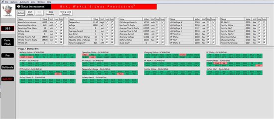
  • My guess is it is some sort of FET control problem, attached is a screen cap of the part that is in the system. The charger is removed, the part is in Discharge Mode but the CHG FET is still on and the DSG FET is off.

  • Pat,

    That screen shot shows that you do not have Impedance Track enabled, so the firmware does not have control of the FETs. Issue an IT Enable (21) command to see if that helps.

    Tom

  • Tom,

    Thanks for that it appears to have helped. So what should Update Status be set to in the Golden Image file now? I've read so many different app notes that say so many different things I'm confused. This is a system side Fuel Gauge.

    Pat

  • Pat,

    You should change the Update Status to 02 in the gg file to create the golden file. It will change to 06 after the IT Enable command has been sent.

    Tom

  • Ok that's what I've been doing I was just concerned when it changed back after I issued the IT command.

    Thanks for your help thus far!

  • Ok my concerns seem to have held true, now that I've re-enabled the IT the gauge is easily confused, it's showing 20% when there is still a significant amount of charge left (I can tell based on the pack voltage alone). Once I plus it in to charge it will read 100% after charging for a half an hour or less. 

    I'm confused as to how we differentiate between a gauge which is learning through cycling and a gauge which has learned and is now in normal operation, the flags appear to be set the same way.