This thread has been locked.

If you have a related question, please click the "Ask a related question" button in the top right corner. The newly created question will be automatically linked to this question.

BQ24074 behaves strange when connected with a GSM module!

Other Parts Discussed in Thread: BQ24074, BQ24050

Hi All,


I am working with a BQ24074 1,5A Li-Ion Battery charger and have a question. What could be the reason why the PGOOD Led is high when connecting a Full charged Battery on my PCB! Normally there should be no LED indication when the Battery is fully charged!

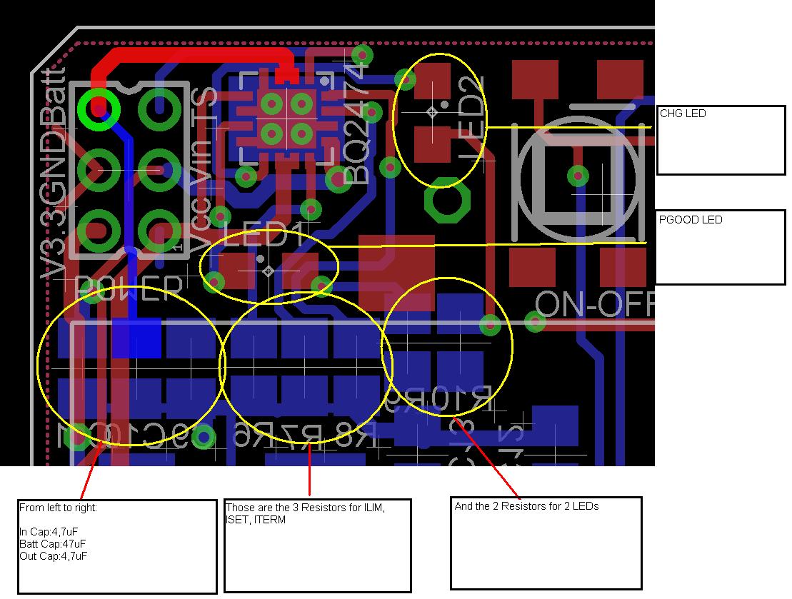
My application is a GSM AVR Module that will have the BQ24074 as a Li-Ion charger. What i realized was that when powering on the GSM module (with a 4,7uF on the Batt Pin) everything is a little bit strange to me! Power consumption is much more higher!


                                                                             With BQ24074 (Not working properly)              Without BQ24074 (working properly)

Power connected(Not turned on yet)                        3-4mA                                                                      1mA

GSM Module ON                                               140mA (not falling when conn.)                     180mA (falling to 3mA when connected to network)


What is suggest is that the GSM module needs 2,3A Picks when starting up and when data are send from the GSM module and i dont know if the BQ can give such a number from Batt to Out.

The capacitors are connected within 1cm range and on the bottom layer (while the BQ is on the TOP Layer)


Kind regards,

-George

  • In the future, please post battery charger questions in the battery charger sub-forum of this battery management solutions forum.  This will help us see and reply to your post quicker.

    PGOOD is not a statement about the battery.  PGOOD will go low (and turn on the LED) if the input supply is good.  From page 25 of the datasheet: "PGOOD is low when (VBAT + VIN(DT)) < VIN < VOVP"

    It is not clear where your current numbers are being measured.  Is it input current into the charger that you are measuring?  Battery current?  Current into your system?  The BQ24074 (which also drives the LEDs) does draw some current from the input supply to operate.  The increase in input current with your system off is most likely the BQ24074 Iq as well as the current being driven through your PGOOD LED.

  • Hi Chris,


    In my case the Vin is very low since there is no power onto attached! I measured some mV (~200) and this exactly is my problem! I don't see any high voltage on the IN pin but the PGOOD goes low and turns on the LED!!!


    The current numbers are measured on the BATT pin in order to see the overall current consumption. I can understand that the the 3mA difference on the turned led on be but why does it not go then back to its normal current consumption (3mA) and stays high on 140mA.


    And the main Question, Why is the PGOOD led turned on with 200mA on the IN pin!!! Could it be on the CAPs? I have tried several values but the same problem!


    I remember i had connected my power supply on the  OUT pin in order to power my board directly without the BQ24074 could it damage the BQ? I guess not?!?!?!?


    Regards,

    George


  • With no input source, Vin should be 0V--not 200 mV.  Either you have a circuit feeding current onto Vin from somewhere else on your board or you damaged the IC when you applied a voltage to the OUT pin.  I would replace the IC just to be sure you didn't damage it somewhere along the line. 

    Without a Vin, the PGOOD LED is always off, on our EVM.  Feel free to order the EVM to test out the charger and confirm the results that you are seeing on your board.

  • Chris,


    Good News! IC replaced and everything works just fine :). I guess i damaged the chip when i connected my main power source on the Vcc of my PCB but which goes also to the OUT pin of the charger!


    So just for the records in case that someone has the same problem DON'T POWER YOU PCB DIRECTLY BUT ONLY VIA THE BATT PIN!!


    Thanks for your help Chris


    Kind Regards,

    George Dellis

  • Chris,


    I need your opinion on this...

    I connected on the BQ24074 a 3.3V voltage regulator in order to power my board with any power source (up to +24V). So the question now is where do i have to connect the bower output of the regulator. Until now i had connected the output of the Voltage regulator on the Vcc of my board but this was wrong since the main power was gone also to the OUT pin of the BQ24074 and destroyed them!!

    My next thinking was to connect the output of the regulator on the IN pin of BQ24074 so that when i have also a Li-Ion Battery connected the battery would always charged and if there is a power failure on the system the Li-Ion battery would continue to power my Board! Am i right? Ok, the main Question now is if this is the right thinking and if the IN pin can handle spikes up to 2.2A in order to power a GSM module.


    Thanks in advance,

    Dellis George

  • What voltage do you need to apply to the Vcc of your board?    Keep in mind that the maximum rating of the OUT pin is 7V.

    The BQ24074 can supply an absolute maximum of 1.5A through the IN pin.  Thus, the additional current for GSM must come from the battery.  In some cases, users connect the GSM system directly to (in parallel with) the battery.  So, for GSM tests, I recommend a voltage on the IN pin as well as having a battery connected to the BAT pin.

    You may want to check out the BQ24050 which supports GSM testing without a battery.