A related question is a question created from another question. When the related question is created, it will be automatically linked to the original question.
If you have a related question, please click the "Ask a related question" button in the top right corner. The newly created question will be automatically linked to this question.
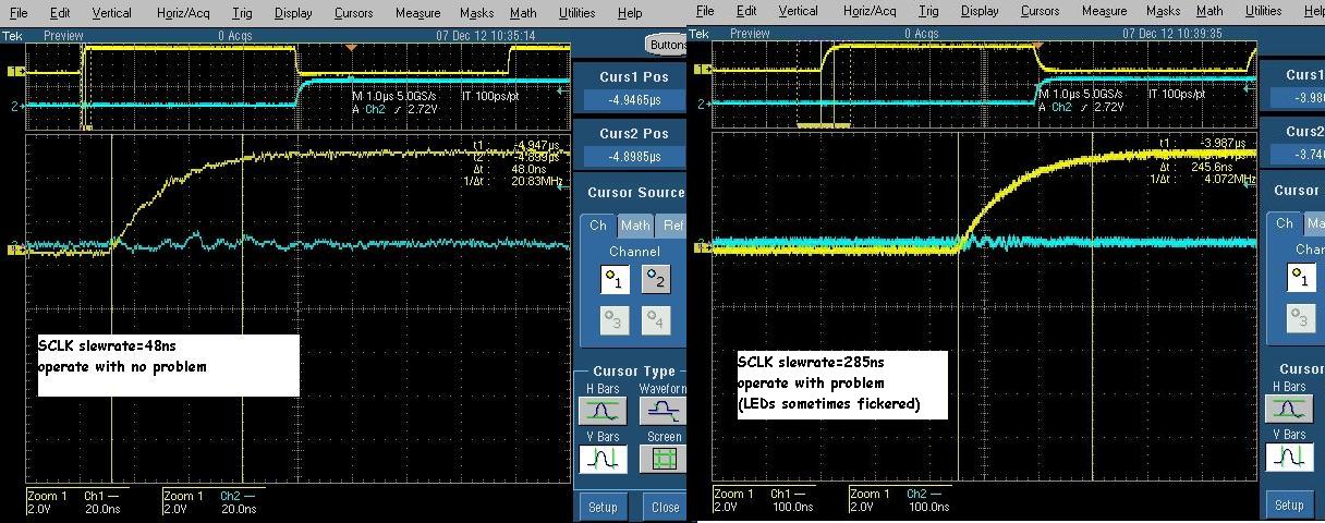
TLC5947 recommend condition and switchingcharacteristics are defind with 1~3ns input rising and falling time as Figure7 and 8 as described by Fig. 7 and 8. But function wise, I think it is no problem even if the rising and falling time of input signal is 1us if setup and hold time of SIN,SCLK,XLAT are enough time with one chip operation (stand alone operation. No cascade operation).
I think the GND line impedance between TLC5947 and controller may be not low. If GND line has some large imperdance, some difference voltage between TLC5947 GND and controller GND is genarated when TLC5947 output turned on and off. Then some wrong data may be written into TLC5947 by SCLK level is recognized as high and low repeatedly around threshold voltage level because of slow rising transient of SCLK.
If this is the reason of the problem, probably the problem is not happend when the data is sent into TLC5947 while BLANK signal is 'H' because TLC5947 output is allways during high BLANK level. Can the customer try the test? Also I recommend you to ask the customer to check how much difference voltage between TLC5947 and controller is generated when the flickering is happend. If the difference voltage is more than 200mV, it may be large. If the difference voltage is large, GND imperdance is needed to reduce by thick wire using or thicker GND pattern or wider GND pattern using.
Can I ask you some questions?
1. How many TLC5947 are cascaded in series?
2. What position IC is the issue IC from controller? Is it the farthest IC from controller? or the nearest IC?
3. Are TLC5947s and the controller for TLC5947 mounted onthe same board? Or is each board separated?
4. What is the SCLK frequency?
5, What is resistor value of the resistor mounted between TLC5947 IREF pin and GND?


