This thread has been locked.

If you have a related question, please click the "Ask a related question" button in the top right corner. The newly created question will be automatically linked to this question.

TLC5927 error detection problem

Other Parts Discussed in Thread: TLC5927, TLC5927-Q1, TLC5926

Hi all!

We are developing a simple LED circuit and are experiencing a bit of a problem with TLC5927 device. We have created a serial protocol by using GPIO. We can control LEDs as well as brightness by entering special mode. The problem arrives when we try to read error status codes.

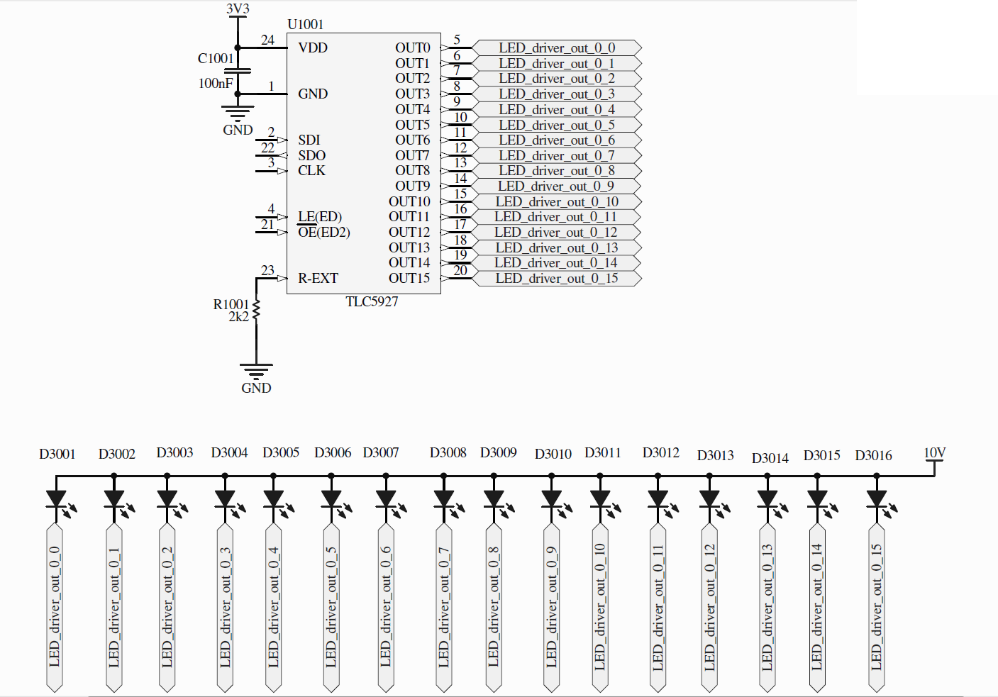
Here is the problem: all 16 LEDs are connected and turned ON. The device ALWAYS reports '0' for all of the LEDs (e.g. error state). We have also tried to short circuit the outputs or left them opened as well. Everything that we tried yields '0'. Any clues?

Bellow is a schematic and scope printout. We have also tried different R-EXT resistors (R1001 = 1k, 560R,...), but with no success. The datagram sent by TLC5927 can be seen in a scope printout. The GPIO pin is set to input direction, but data still remains '0' for all LEDs.

Thank you in advance for your help.

Best regards,

Matej

  • Matej,

    First, note that Error Code will be HIGH on normal and LOW on Fail or NO Detect.  Please see Table 1, Table 2 and Table 3.  You must keep OE low during the full testing of the Error or you will get the "Detection not Possible" LOW.  Please see Figure 13 for the timing.

    I will be out of the office until January 2nd, but expect to keep up with the forum.

    Regards,

    Dick

  • Hi Dick,

    thank you for quick reply. I will comment what you have written bellow:

    ----------------------------------------------

    'First, note that Error Code will be HIGH on normal and LOW on Fail or NO Detect.  Please see Table 1, Table 2 and Table 3.'

    We have turned all the LEDs ON. The 'NO detection' is therefore not logical state. Why we get '0', eventhough the LEDs are tured on and working, i do not know.

    'You must keep OE low during the full testing of the Error or you will get the "Detection not Possible" LOW.  Please see Figure 13 for the timing.'

    I see. The document also states, that 4 clock cycles in a 20us or more are enough. We have also tried 10 or more clock cycles with OE low but it didn't help.

    Please see the scope picture attached. I belive that the timing is in accordance with Figure 13.

    ----------------------------------------------

    The problem is, that we have measured signals with oscilloscope and we belive that it is in accordance with figure 13 (see the attached picture). Maybe there is something we are no seeing here?

    Thanks for the support,

    Matej

  •  Hello,

     I'm facing exactly the same problem with the same TLC5927 Chip...

     This chip is conneted through SPI to a 8051 microcontroller.

     Everything is OK, can set LEDs perfectly.

     I can send configuration code to change the intensity in the LED => All is OK (Even if it was not easy to make everything work only with the specs !)

     Now, I'm not able to read error from the differents channels...

     I have followed all recommandations, but SDO wire remains to zero volts ...  Looks like all channels have an error, but it doesn't look to be the case...

    We don't have a quad channel color oscilloscope, so I'm not able to give a screenshot, but it almost the same than the Tekro provided here.

     Do you have any clues to help me or maybe pseudo code or 8051/C code ?

     Thank you for your help !


  • Yannick,

    I do not have any code on error verification that I can send.

    Have you monitored SDO during normal operation to verify the SDO shows SDI delayed by 16 cycles?  

    For an output to show the correct error message, the output must be turned ON and OE must be low (the LED should be on).

    Regards,

    Dick

  •  Dick,

     I have checked this morning...

     I can see on SDO wire the SDI delayed by 16 cycles.

     Note that I can read something on the first SDO burst. Sound strange because nothing was send on the SDI wire previously !

     Very strange, all others mode of the TLC works well,

     The SDO wire remains desperatly mute when I want to extract the error code. Does it mean that all channel in error ?

     I don't think so, everything looks to be OK...


  • Yannik,

    You can see data on SDO during the initial SDI clocking.  This is the default power up of the registers and is ignored.

    I do not think all channels are in error.  I will do a bit of checking in the lab to see what I can send to you that may help.

    Regards,

    Dick

  • Hello Dick,


    I'm a colluege of Yannik and in charge of hardware dev.

    I will now make the PCB on the CAD to route the TLC5927.

    I'd like to use the TLC5927PWP package because of it's special power pad adapted to evacuate the heat.

    But I could not find in it's datasheet any rule where to connect electrically this power pad.

    Question:

    Can I connect it to a copper plane that is connected to the 0V pin of the circuit?

    Or must it be connected to the VDD pin?

    Or must it be left float?


    Thanks for your reply,


    Best regards,


    Philippe G.


  • Philippe,

    see TLC5927-Q1 www.ti.com/litv/pdf/slvs973, page 3 :
    -> Exposed Thermal Pad : Connect to GND. The thermal pad should be soldered to ground in all applications.

    Regards, Bernd

  • Hallo Bernd,


    Thanks. I had an older version of the datasheet from july 2008 where it was not indicated.


    Beste Grüsse,


    Philippe G.

  • Hi Matej,

    Did you ever get a resolution for this problem?  I am having the same issue with the TLC5926.

    Thanks!

    Matt

  • Hi Dick,

    Was there ever a resolution to this?  I am experiencing the same problem with the TLC5926.

    Thanks!

  • Matt,

    We don't have a full resolution.  We are able to complete the error read back using the MSP430 LaunchPad, but do have some intermittent issues.  The engineer we had actively working is not available to continue at this time.  We will assign to another engineer to continue the effort for full resolution.

    Regards,

    Dick

  • Hi all!

    We have tried a lot and at the end of the day it turned out that power supply voltage was the issue!

    We resolved this some time ago and as far as i remember, the OUT RTh parameter was the issue (check table in datasheet page 8). Basically it says, that you have to provide at least 2.2V on the driver the pin in order for detection to work. So, if you have a voltage drop of 3V on LED, you have to provide AT LEAST 5.2V on Vdd pin, or the circiut will say that you have shorted pins. The same was for open-pin detection.

    So all-in-all you have to find a range of Vdd voltage for your specific application. The main parameter for detection to work properly should be your LED voltage drop.


    Hope it helps,

    Matej

  • Thank you, Dick.

    I have been working on this from the firmware side for over a week.  I think I found a work-around, but I want to be sure that my results are consistent; So I have a few more tests to run.

    What I have found is that the first time I enter special mode after power-up, I always receive 0's on all bits (I have three of these drivers cascaded).  If I return to normal mode and repeat the process, the data appears (so far) to be correct.

    I have tried other attempts in the hopes that all my reads (including the first after power up) would be correct.  I have entered a delay after setting the LEDs and prior to entering special mode, however the first read returned the same result.  I have also noticed that if I only use three clocks with the `OE line low that I always get all 1's (my timing is correct as `OE stays low for well over 2us), even on outputs that are not connected.  If I have four or more clocks the data is all 0's on the first read and correct on all consecutive reads.  Here is the method I am using:

    1.  Latch 1's in all bit locations to drive LEDs.

    2.  Enter special mode.

    3.  Set `OE low for 4 clock cycles (appx 200us at my clock speed).

    4.  Set `OE high and clock data back to microcontroller.

    5.  First read is always 0's... each consecutive read (conducted by repeating all of the above steps with the exception of step 1) after the first returns correct data.

    Again, the above is preliminary and I have more testing to do.  Please let me know if you have a similar issue.

  • Matt,

    I have heard from other users that sometimes their systems require entering special mode 2X (back to back) to consistently enter special mode.  I have not been able to duplicate that.

    Your method will work as you show above.  If you find a more robust method, please let me know.

    Regards,

    Dick

  • Hi

    We were having a similar problem, and worked out it was always faulting because the voltage between the LED and the TLC5927 was too high. Try changing the supply voltage of the LEDs so that the Vth is below 2.4V and then running the test again.

    Cheers

    Anthony