This thread has been locked.

If you have a related question, please click the "Ask a related question" button in the top right corner. The newly created question will be automatically linked to this question.

TPS54325 Odd Enable Reaction

Other Parts Discussed in Thread: TPS54325, ALLIGATOR

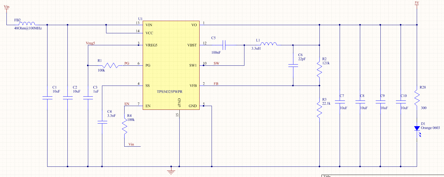
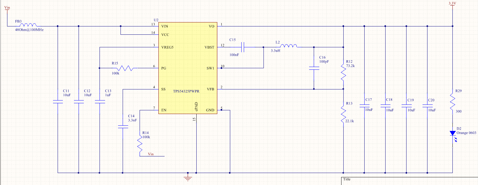
I'm got 2 almost identical circuits based on the TPS54325. One is generating 3.3V and the other is genrating 5.0. The capacitor between Vfb and the inductor is 22pF for the 5.0V and 100pF for the 3.3V circuit. The only other difference is the upper feedback resistor.

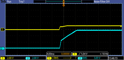
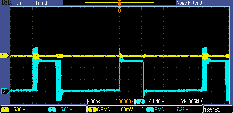
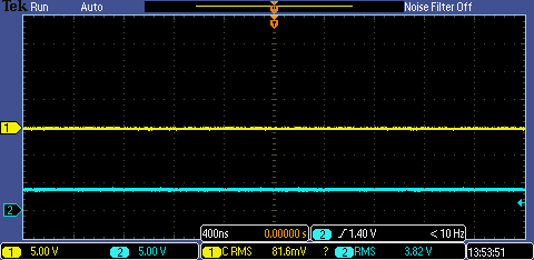
Both circuits are fed from the same 12V source and right now I do not have any load connected. The 3.3V circuit fires right up but the 5.0V circuit very briefly come on (no scope on the production floor here but I have a LED on the output). PG is 0V and the high side of the enable pull up is 12V. As soon as I probe pin 7 or the side of the pull-up resistor connected to pin 7, with my volt meter the circuit starts working and stays working until I remove power and try again.

Maybe because it's Friday afternoon but what's up?

  • Seems like a soft start issue? If I power cycle my bench power supply I get that behavior but I just disconnect the power cable from the board and plug it back in the circuit works fine. So there's still a problem that for some reason is only showing up on the 5V circuit. The enable pull-up is 100k, maybe I'll reduce that. Without a scope here I'm a little blind. :(

  • How many circuits do this?  Only one?  It sounds like it may be a solder process problem.

  • I had 2 boards built up and they both act exactly the same. I've got 100k pull-up to Vin on the enable pins.

  • The EVM uses 10 k.  You might try that instead of 100k.

  • I'll probably try some testing over the weekend but I'm hoping that's all it is.

  • OK, it's not the pull-up on the enable pin. It's at 10k now and I'm getting the same results. I verify that I'm getting ~9.5V on the enable pin with a 12V input. What's a bit odd is that Vreg pin measures ~5.7V when there is no output so it seems like the chip is working but just not enabling the output for some reason. It's not a short because once I get the circuit to work I measure 5.0 V on the output (although all of this testing is with almost no load).

    I have a different power supply here and it acts the same, if I power cycle the power supply the 5V doesn't come up. If I leave the power supply on and unplug/plug in the power cable to the board the 5V rail comes up.

    I've got 3.3nF between the SS (pin 4) and ground.

    Here's the circuits and board layout. On the board layout the 5.0V circuit is on top and note that the TPS54325 is rotated (pin 1 is in the lower right corner of the picture)

  • The schematics seem ok.  You might try shorting on the ferrite on the input.  Otherwise I'll have to see some waveforms.

  • OK, I'll try that in a while. Which waveforms would you like to see?

  • Just shorted the Ferrite bead (FB2) and now when I power cycle the bench power supply the 5V rail does come up just like the 3.3V rail. I'm using a NIC NCB-H1206B500TR600F, which is rated at 50 ohms at 100MHz, 0.020 ohms max DC resistance and 4A.

    I'm a little confused, what's going on?

  • On a side note, one of the 2 boards that we built I can't get the 5V rail to come up. The incoming ferrite bead has been removed and replaced with a jumper wire (it didn't come up before doing this either). I'm measuring 1.2V on Vreg5 pin, enable pin is at 11.7V, and PG is 0V. I guess I'll hook a scope up to PG and see what it's doing and if it's ever high but since it's being pulled up to Vreg5 and Vreg5 is only at 1.2V there's something causing Vreg5 to not be 5.5V which is odd

  • The internal UVLO runs off the VREG5 pin, rather than the actual Vin. If VREG5 is out of regulation, then the device is latched off.  I am thinking this may be an issue with very slow Vin ramp up.  I'll need to see Vin, VREG5, SW and Vout to start with.  You can provide as much information as you can, more is better than less.

  • OK here's the scope plots, Ground is just on a short wire I attached to the input cap near the 5V Switcher and using 2 alligator clips. Channel 1 is the 5.0V Switcher and Channel 2 is the 3.3V switcher. 

    Vin coming from 12V Bench Power Supply

    Vreg5

    Switch Pin

    Vout


  • On your 5 V supply, VREG5 is not coming into regulation.  it should look the same as the 3.3 V supply.  You may have damaged the IC.  Try replacing it.

  • OK, that will have to wait until Tuesday as I left all the parts on the production floor and it's closed tomorrow.

    Still don't know why I can't have the ferrite bead on the 5V incoming rail. Should I take a scope plot of Vin on both rails after removing the jumper across the ferrite?

  • I just wanted to close the loop on this thread in case someone else comes across it. I did replace that switcher and it did die somehow.

    After experimenting with just about everything the problem of the 5.0V switcher not coming up was solved by changing the 3.3nF cap on the SS pin to 33nF. Once I did that all 3 bench power supplies that "didn't work" before now work flawlessly.

    I've been debugging some other issues but one other item that I'll change is that the cap between VFB and 5V has different values in the datasheet (10-22pF) and the EVM (220pF).

    For some reason I had 100pF on the 3.3V switcher and 22pF on the 5.0V switcher. I'm using 330pF on the board on other locations, would it be OK to use 330pF? I don't see much information on what the feedback cap is doing.

  • John,

      Is there a MAX Ramp TIme for VIN?  I don't see any spec in the datasheet.

    Does the Tss for SLOW START time have to be set greater than this ramp time, per Equation 1?

  • There is no specified time.  But you have to use some common sense.  For 5 V regulation, the input voltage needs to be around 7.7 V.  Since the UVP is activated at 1.7 x the SS time, the input voltage needs to be above 7.7 V before that time.  You have to time your SS relative to your input voltage ramp.  Alternately, you can just hold EN low until the input voltage is ramped up to its nominal value.