This thread has been locked.

If you have a related question, please click the "Ask a related question" button in the top right corner. The newly created question will be automatically linked to this question.

TPS40210, overcurrent/duty problem

Other Parts Discussed in Thread: TPS40210

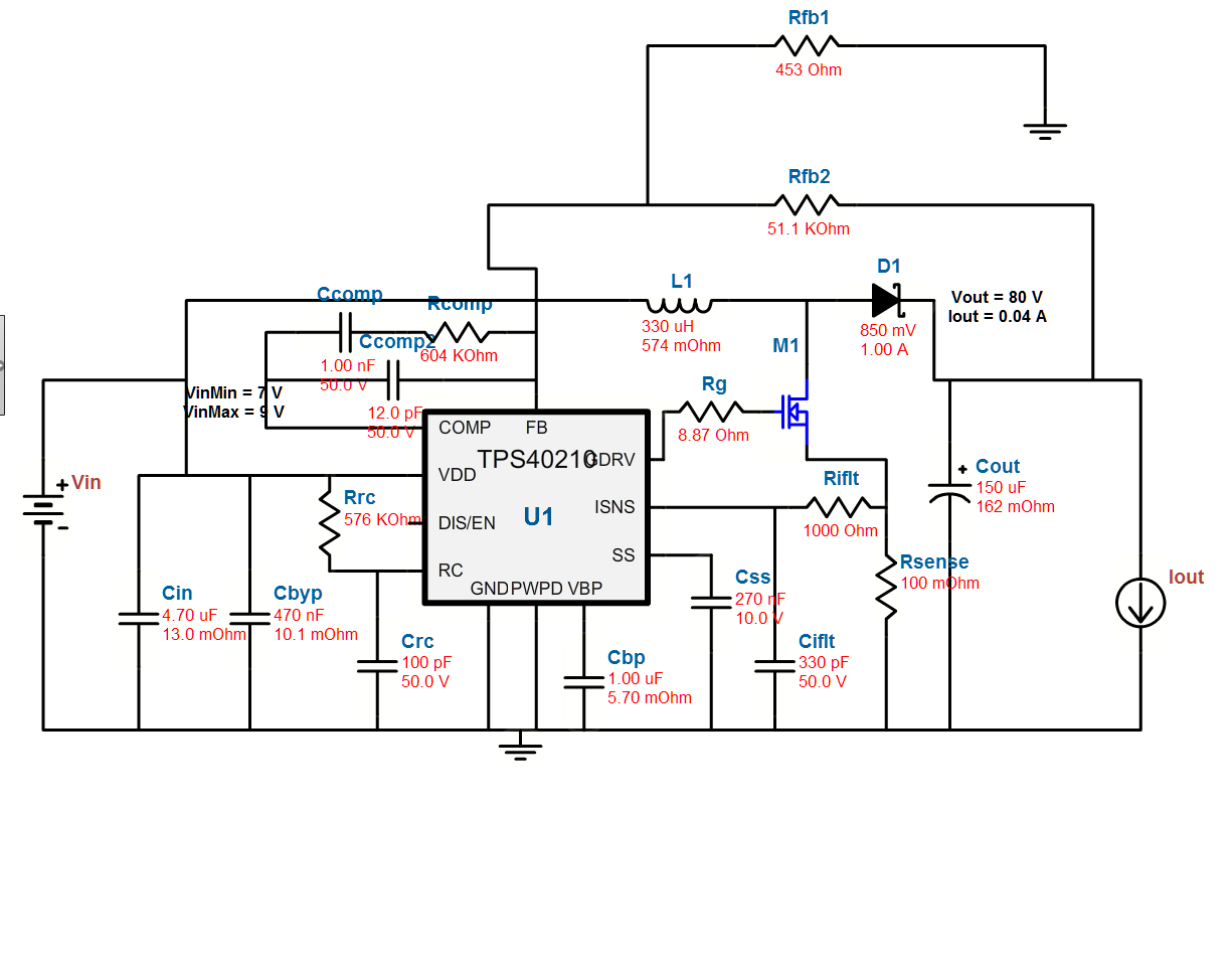
Spec: 9V in, 80V out @ 40mA

I used webbench for the design, 

The first problem is that it has trouble starting, since very quickly after it starts current overprotection kicks in and PWM turns off while SS drains. This can be overcome by shorting the sense resistor for a second, or slowly ramping up the input voltage. I assume a larger capacitor on the SS pin would help?

The main problem is, the output voltage isn't being reached, so the chip seems to be maxing out the duty cycle to try and increase output voltage, ignoring current, etc. The Duty cycle is ~97%  is too high, to the extent of decreasing returns, so the duty cycle need to actually decrease for the output voltage to increase. A side effect is that the current through the inductor and mosfet is much higher than it should be causes significant heating. 

Some quick questions, is the current sense circuitry suppose to adjust the duty cycle when the ISNS pin shows the current is getting high, or does it just turn off the PWM output? It would be nice if the controller could adjust the duty cycle to prevent an over-current shutdown. 

Is there a way to limit the duty cycle?(increasing switching frequency?) Am I missing something?


  • Hi Jesse,

    A larger cap on the SS pin would be the first thing to test. The slow start works by ramping up the reference voltage of the TPS40210 which should be limiting the duty cycle. I would not expect it to operate continuously at 97% duty cycle. Additionally the TPS40210 uses hiccup current limit meaning the PWM output turns off when the over current threshold voltage at ISNS is reached.

    With the high duty cycle application you may want to consider a lower switching frequency to increase the off time of the FET.

    Can you show some screenshots of the start up? I would like to see the voltage at the gate of M1, the drain of M1, Vin and Visns. Please have a zoomed out screenshot and one which zooms in at the moment the device turns off. Also is there a load on the output during startup? This increases the current needed at startup.

    Best Regards,
    Anthony

  •  I put a 1uF on the SS pin. 

    I put a 470pF and 1000K Ohm resistor on the RC pin.

    If I use a Vin of 9V I get the hickup current limiting, and the 1uF on the SS pin takes a while to discharge. 

    With 5V in, it doesn't hickup but the duty cycle is 99% (200ns/20us), 5V vin, drawing 722mA. 14V out with a 2.2k ohm load. 

    I'm sorry I don't have time for any screenshots at the moment, it's quite hard to capture anything, since when it is in hickup mode the the 1uF capacitor is so big it takes so long to discharge I'm having trouble getting the oscilloscope to trigger in the first place. Hopefully I'll be able to get some screenshots to you some next week. 


  • Jesse,

    Thank you for trying the larger SS cap. Was a 1000 Ohm or 1000 KOhm resistor used? It should be 1000 Ohm.

    Stability or max duty cycle might be limiting the performance. A couple other tests to perform are as follows. I recommend doing one at a time.

    1. Reduce Rg to speed up turn on of the FET.
    2. Adjust compensation components. First I would try increasing Ccomp to 0.047µF lowering the frequency of the zero.
    3. If this doesn't work, to lower the gain of the compensation Rcomp should be reduced. Please try Rcomp = 300k, Ccomp = 0.1µF and Chf = 100pF.

    Once screenshots are provided I might have an idea as to what the on time is and if a lower switching frequency is needed to increase the maximum duty cycle.

    Best Regards,
    Anthony