This thread has been locked.

If you have a related question, please click the "Ask a related question" button in the top right corner. The newly created question will be automatically linked to this question.

Help with LP2953

Other Parts Discussed in Thread: LP2953

Thanks for the reply I'll check that out and post back when I get a chance.  

I've got one more question.  I've got a circuit using the LP2953 to charge a single cell NiMH battery.  It works fine until I get close to the 1.23v comparator reference.  Once my feedback pin sees something like 1.19 -1.2 volts my current gets cut in half.  I'm confident in the rest of my circuit because when I ground the feedback pin i get my expected 200mA current into the battery.  Also, when the battery voltage is low from being used (like around 0.9v) I get the full 200mA for a long time until again, my feedback rises to a value pretty close to the 1.23v threshold. Does this make sense?  I assumed that until i hit the 1.23v on the feedback pin the error amp would drive the transistor so that it conducts completely and when the feedback pin hits 1.23 volts it shuts off, but it seems like there is some grey area where it is on less or something the closer to 1.23v I get.

I'm using the input-output pins to sink current through a bjt which is my constant current path to my battery.  It seems like the closer I get to Vref the less the error amp is on and therefore I get less of a current sink on my bjt which means it isn't on enough.

Here is a rough image of my circuit just to give you an idea of what I'm doing.  I've changed some of the R values, but this gets the idea across.

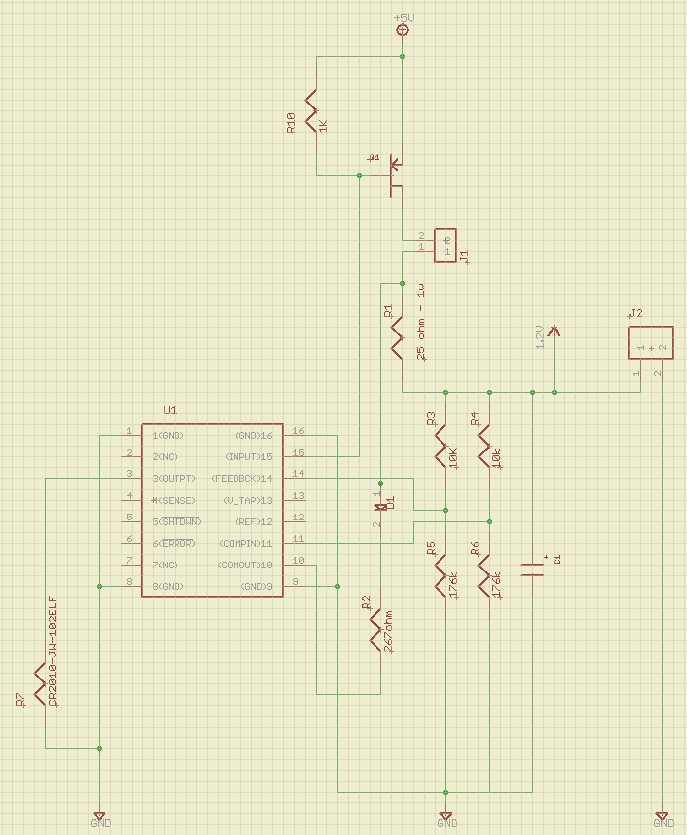
I'm charging my battery up to ~1.46 volts. With my current R values (not the ones shown on the schematic) I get 200ma through the device until my feedback pin gets to about 1.19 volts.  Shouldn't this give me constant current until I reach the 1.23?  I've also tied the error pin high on my breadboard and that hasn't helped either.

Thanks again!

  • " ... Once my feedback pin sees something like 1.19 -1.2 volts my current gets cut in half... "

    My best guess, based the description of the behavior, is that the circuit is unstable in the linear region. Check for oscillations when operating in the "grey area".


  • Yea, I thought that might be the case.  I've tried some different output capacitors and only get a small amount of improvement.  I started with a 470uF that worked as described above.  I've changed that out for smaller ones..all the way down to 1uF and it seems that with a 47uF I get a little better performance.  With the 47uF I get about 100mA through at the moment when my battery is at ~1.4 yielding about a 1.2 volt potential at the input of the error amp.  

    It turns out that when I put my meter probe on the feedback pin to measure voltage my auxiliary amp output (which drives a transistor controlling an LED) switches on and off a lot making the LED flicker.  Is this normal  because I'm probably right on the threshold of the comparator (error amp)?  It looks like this kind of substantiates Donald's post that my system is unstable.   Any tips on fixing a stability issue with this part?  

    I'm basically trying to do the same thing as in figure 8 of:

    http://www.ti.com/lit/an/snva557/snva557.pdf

  • For Figure 8 "... C2 is used for compensation ... "


  • Yea, I read that in the pdf.  I put C1 (the compensation cap) in last night and didn't help.  I don't have access to a scope so I'm not able to look at any waveforms which is kind of lame.  Thanks for your help so far.  I'll continue to work on it.

  • In this case, without a 2-channel scope it's tough to know the basics for stability: how much phase shift is involved, at what frequency is the oscillation, and does any particular tweak make the situation better or worse.

  • I agree.  Thanks a lot for the help.  I'll revisit this topic when I get the capital to buy a scope.  It basically turns into a trickle charger the closer I get to my target voltage so this isn't a big deal.  Thanks again!

    Robbie

  • So I've gotten a scope and probed around the circuit quite a bit.  After spending more time on this it seems like there has to be oscillations in a circuit using this chip because you're battery voltage feed back will hit 1.23V and when you turn the BJT off (from what I understand this is done by the comparator in the LP2953 releasing it's output so the gate of my BJT Q1 can be pulled up to VCC) the voltage will probably drop a little and turn the comparator back on.  Is this correct?  

    Also, after checking the circuit out with a scope I found why it is drawing less current as I reach 1.23 and actually still draws a little current after 1.23V is present on the feedback pin.  For some reason, right around 1.23V on the feed back pin Q1 is still on a little bit.  Does anyone have any idea why this would be the case?  When I short the output it turns completely on without any problems and when I open the output it is completely off, but for some reason I'm getting stuck in between.  I've tried stronger pull-up resistors for the base and that didn't seem to help.  I've got a 1K pulling up the base and a 200 ohm on the output pin.  Any help would be greatly appreciated....I can't seem to figure out why the BJT is acting like this.

    Thanks,

    Rob

  • "... the voltage will probably drop a little and turn the comparator back on.  Is this correct? ..."

    If current goes from something to zero, I would expect to see some small change in the voltage.

    More likely you will get to some steady-state point where the current vs. voltage are balanced ... i.e. constant voltage trickle charge ... unless there is some voltage detection, with hysteresis, outside the loop to sense 'charge complete'