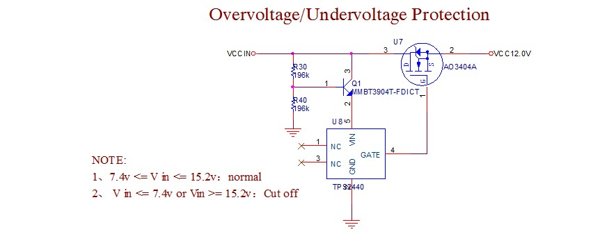
above picture is my circuit, can you help me analyse whether there is something wrong with the circuit.
I am sorry the tps2400 can not work normal every time when it power on.
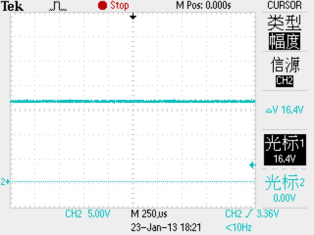
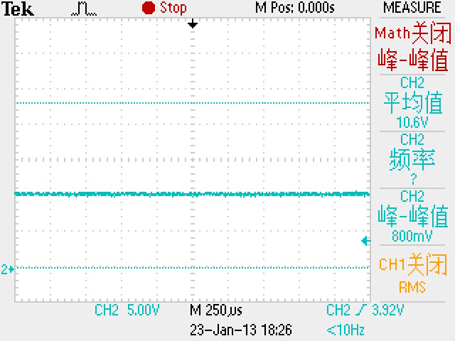
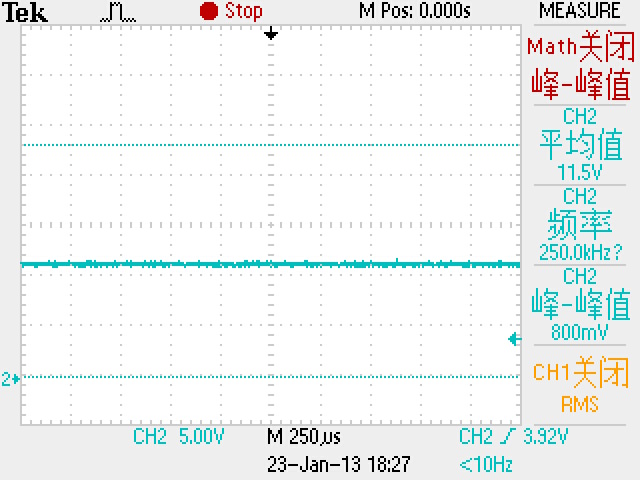
The voltage of VCCIN is about 10.5v.
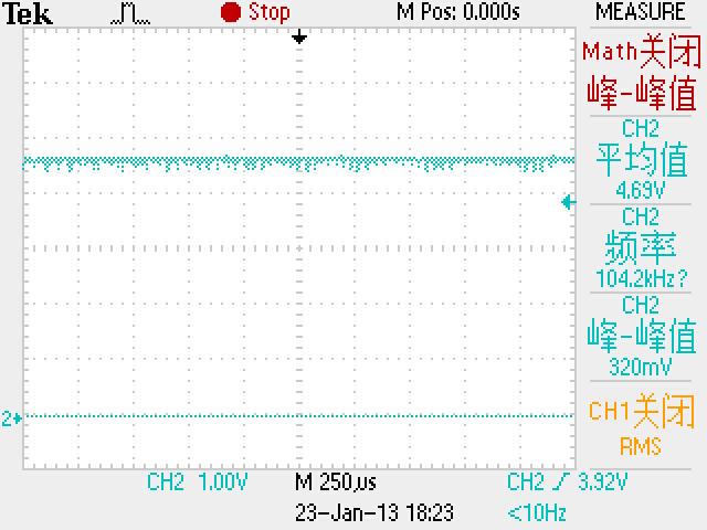
the pin5 of tps2400 is 4.69v, the level of pin4 is 1.9v, the nosfet is shut off.
the event does not happened everytime!
best regards
linjie pan