A related question is a question created from another question. When the related question is created, it will be automatically linked to the original question.
If you have a related question, please click the "Ask a related question" button in the top right corner. The newly created question will be automatically linked to this question.
Thanks Donald, you are correct, with some capacitors I can see an oscillation even with 10uF ceramic. ESR varies with frequency but most ceramic capacitors have better than the 0.3 to 8 Ohm ESR recommended in the datasheet.
I have tried various brands and types of ceramic capacitors, any visible oscillations on the output stops most of the time, but the input is still 3 to 6mA. I have tried up to 47uF ceramics on the output. The input and output caps are located at the Input and Output pins of the IC to ground.
Do you have any recommendations, as I have 2000 boards about to go input production.
Better I meant less than 0.3 ohms, which could be a problem.
However, if you look at page 9 of the datasheet, at lower current the ESR = (0.01, 8) ohms
I cannot see any oscillations on input or output.
I have tried various vendors' ceramics from 10uF to 47uF, including parallel combination with 100nF.
I have increased ESR by adding additional external resistor in series with output capacitor - makes no difference, still large Iq.
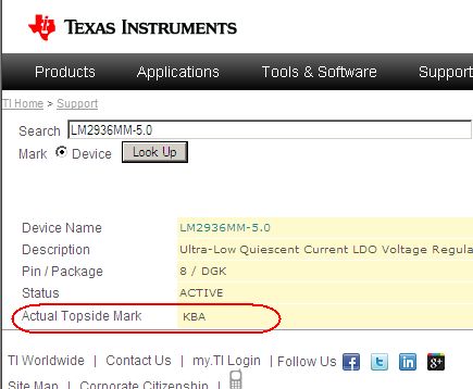
This problem is happening with both LM2936M-5.0 and LM2936MM-5.0.
I have just tried an LM2936Z-5.0 (TO-92) initially on a bit of matrix board, and then on my actual PCB, in both cases, there are NO problems, works with a low Iq, whereas SO packages draw 3 to 5mA.
At this point I am out of ideas. From the described behaviour these LM2936M-5.0 devices would seem to be non-conforming parts.
I suggest that you contact your supplier, or your local TI sales offices, to return and get replacement parts.
TI has an established method for initiating and processing returns via TI's CUSTOMER Return Material process. For information on how to process returns, please contact your CUSTOMER service representative, TI authorized distributor or TI's Product Information Center.
I agree with your thoughts. Problem is I have two chains of supply, in Australia parts are from element14, and our production parts in China are from a distributor in Hong Kong. The problem exists from both sources of supply for both the M and MM package.
I tested over 100 boards yesterday and they exhibit the same problem (HK supply). There are another 900 assembled boards in Shenzhen, and another 1000 going into production on 16th Feb. The consequence of this problem is a higher standby current which prevents battery operation of the product but this is not a show stopper. I am just uncomfortable with putting a product in the field with a known problem.
Ultimately I will update the design to use another regulator.
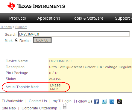
There is mis-match against what is documented at the TI web site for the LM2936M-5 top side marking
Should be LM293 and 6M-5
Your marking shows an extra ".0" in the voltage option.
I need to find a sample here to confirm but I think there should be 3 lines total : Logo&DateCode, LM293, & 6M-5
Only way to know for 100% sure is to have the expoy package etched away to reveal the die.
There is a formal procedure for submitting devices back to TI for failure analysis to get this "de-cap" done. That would need to go through your local TI sales office, or your supplier, since there is some paperwork needed upfront.
I have received and tested my boards with 25 x LM2936M-5.0 from element14, and 3 x samples from TI.
In most cases the voltages regulators worked perfectly ( low Iq), except for 2 that I found the output capacitor value was low ( ~ 6uF instead) of 10uF - increasing this capacitance fixed all problems.
All the new ICs were labelled with 3 lines of text, for example :
MZAC LM293 6M-5
whereas all the Chinese sourced parts had 2 lines of text with the extra ".0"
I am trying to get procure information from my supplier in China at the moment, and will advise once I have this. I would also like to return some of these parts to TI for inspection - please advise to contact and procedure.
I am expecting another 200 units to come in tomorrow from element14 - will advise to progress.
If the links don't work, then they might be for internal use only. My apologies if that is the case.
Unfortunately, per TI corporate protocol, I am not allowed to receive any samples directly for analysis. They need to be logged in and accounted for by the QA/Reliability group.
Best option is to your contact local TI sales office for support.
This could be reported as 'out of compliance' since the ground pin current is excessive, or 'suspected counterfeit 'due to excessive current and device marking.
Meanwhile, I will check with local (Santa Clara, CA, USA) QA/Reliability group today to see if there is some way to them into in our local lab for analysis.