This thread has been locked.

If you have a related question, please click the "Ask a related question" button in the top right corner. The newly created question will be automatically linked to this question.

LMZ23605 / Vout adjustment by DAC

Guru 20090 points
Other Parts Discussed in Thread: LMZ23605
Hello,
 
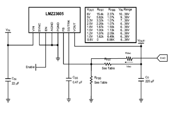
I use LMZ23605 by attached circuit.
 
DAC is connected to FB pin of LMZ23605 via Rdac.
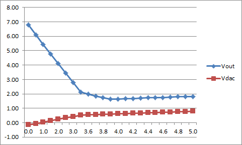
DAC voltage will be increased , Vout will be decreased.
But, there is difference result between Iout=1A and Iout=0A.
 
Please see the attached picture as Vout vs VDAC(DAC output Voltage) at the conditoin of Iout=0A. 
VOUT is increased when VDAC is over 4.0V.
Could you please kindly let me know this reason ?
 
At the conditoin of Iout=1A, Vout is not increased by VDAC.   
Vout is decreased always at the VDAC range 0V~5V.


Best Regards,
Ryuji Asaka
  • Hello Ryuji - Our team is taking a look at this.

    Best Regards,

    -JPF

  • Hello Ryuji,

    This is an interesting situation. It looks like you are trying to obtain a 0 to 7V output voltage using the DAC adjustment of injecting current in to /(out of) the feedback node.

    In general, most step-down regulators will have issues once you attempt to control output voltage below their internally establish reference voltage. In the case of the LMZ23605 this reference voltage is 0.8V. The primary issue has to do with minimum duty cycle limits. Additionally, with the LMZ23605 there is a control loop mechanism that attempts to prevent reverse inductor current at light loads.   This control loop mechanism will override the Dac control current into the feedback pin and prevent further decrease in output voltage.

    In light of that We have two suggestions that you can try.

    1) Rather than the three resistor approach. drive the bottom end of RFBB with a buffered DAC control voltage. The incoming  0..5V DAC control  olatge should be divided to be 0.. 0.8888V using two resistors. Then buffer that control voltage with a unity gain follower op amp. The select 1.00k for RFFB and 9.00k for RFBT. Give that approach a try.

    2) Provide some minimum loading in parallel with your actual load.  Though it might also be necessary that the dummy load current be sunk to a negative voltage potential.

    Alan Martin