This thread has been locked.

If you have a related question, please click the "Ask a related question" button in the top right corner. The newly created question will be automatically linked to this question.

LP2951 - Stability problems when connecting a load-resisistor between LDO-ground and supply-gnd

Other Parts Discussed in Thread: LP2951

Hi everyone,

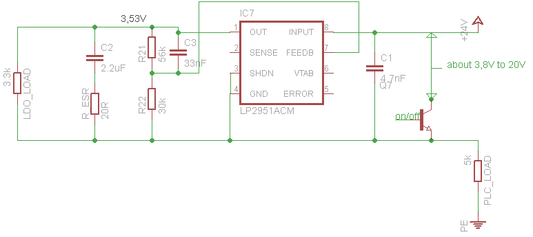
I use the LP2951 in a special configuration. A schematically picture is added below.

The problem is, that the ground of the LDO lies not on the power-supply-ground. Between power-supply-gnd and LDO-gnd is a resistor that is variable.

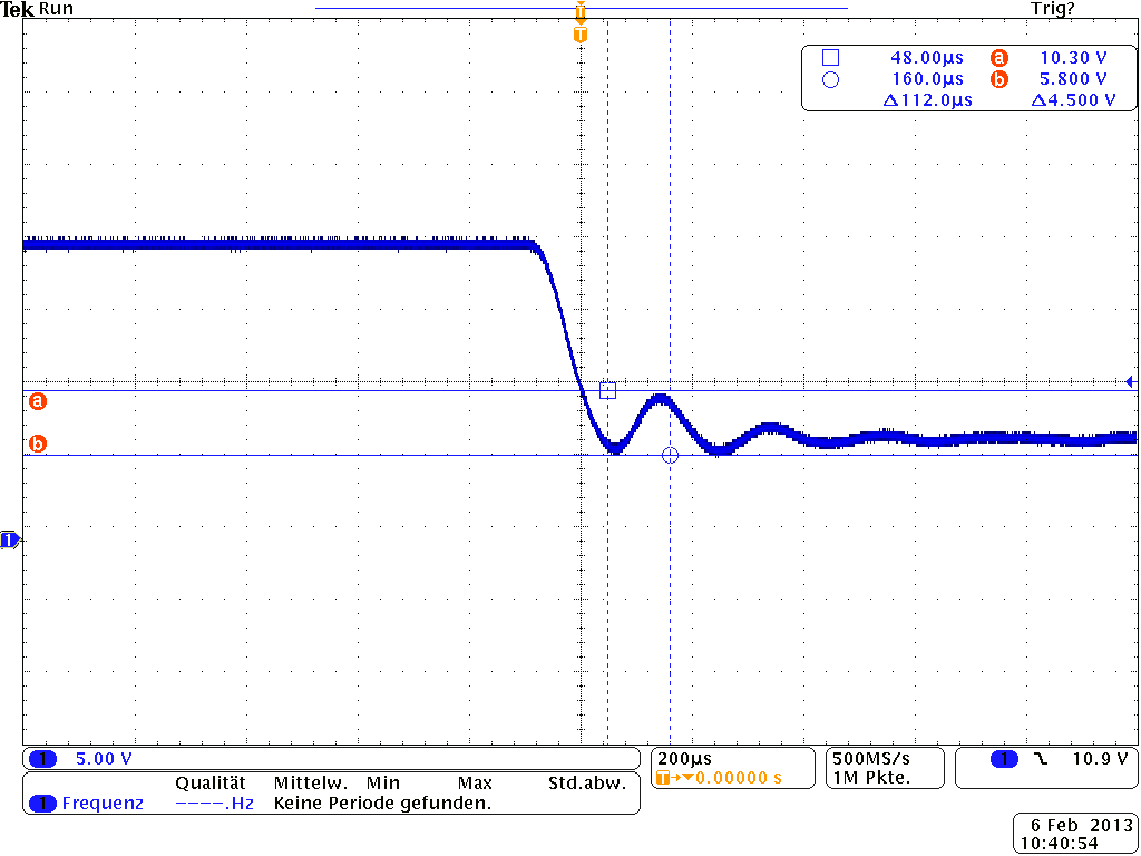
Because of this the LDO runs NOT stable. It comes along, that the input-capacitace of the LDO must be small for my application.

If I raise the ESR, the LDO runs stable. Why is this so? How can I simulate bode plots or something like this to visualize and explain the problems?

Are there formulas for this configuration, that gives the poles and zeros?

Regards


  • I doubt that this is a phase margin (i.e. poles and zeros) issue. If you remove (i.e. short) the variable 100 Ohms to 10k Ohms load the LP2951 behaves normally, yes?

    You have introduced a high impedance to the input supply. Normally, this would compensated for by increasing the value of the input capacitor to create a low source impedance from Vin pin to the GND pin, however that appear to be counter to your application needs.

    Differential voltage waveforms between the Vin pin and GND pin, and the Vout pin and GND pin, may be revealing.

    " ... If I raise the ESR ..."

    I presume that this is Cout ESR you raised, yes? How far did you need to raise the ESR to get the LDO to run stable?


  • Hi Mr. Jones,

    thank you for the answer.

    Yes, I raise the ESR of Cout. I have added a resistor in series with Cout. With a value of 20 Ohms the LDO runs stable!

    I can't explain why. Have you an idea or explanation.

  • If you need to go that far with Cout ESR then this may be a case of 'poles and zeros' after all

    The Load pole is approx 5.8Hz, and the extra 20 ohms will not have any measurable affect on it.

    For LP2951 you would normally want a single zero somewhere between 10kHz and 50kHz, from either Cout ESR only or from Cff (i.e. C3) only.

    The Cout ESR zero is at about 1.7kHz (4.7uF & 20 Ohms).

    Simultaneously, C3 (2.7nF) along with R21 (56k) and R22 (30k) create both a zero at appox 1.1kHz and a new pole at approx 3kHz.

    With C3 set to such a large value (120pF to 180pF is more appropriate), it's possible that you have tuned the Cout ESR to some sweet spot where the Cout zero cancels out the added C3 pole.

    My suggestion would be to simplify the circuit by (choose one):

          > removing C3 and dealing with Cout ESR only (try 1.0 ohm)

    OR ...

          > set the ESR resistor to zero, and deal with C3 only (try 180pF)


  • Thank you for the answer,

    I think i must go more into detail...
    The Voltage "about 3,8 to 20V" is switched by a transistor.
    That means, that when the transistor is switched on, 3,8V lies at the LDO-input.
    If the Transistor is switched of, 20V lies on the LDO-input. This is more illustrated in the picture below.

    My current values for the devices are:
    C2=2.2uF, C3 = 33nF. LDO Load about 3.3k-Ohm.

    I have test your recommomdation which have no effect.

    In the picture below, I measure the signal over PLC_LOAD.
    The picture shows the signal, when I turn off the transistor.
    Without the ESR I see ringing, which suggest a small phase-margin.