This thread has been locked.

If you have a related question, please click the "Ask a related question" button in the top right corner. The newly created question will be automatically linked to this question.

LM5088 - stability question

Other Parts Discussed in Thread: LM5088

Hello,

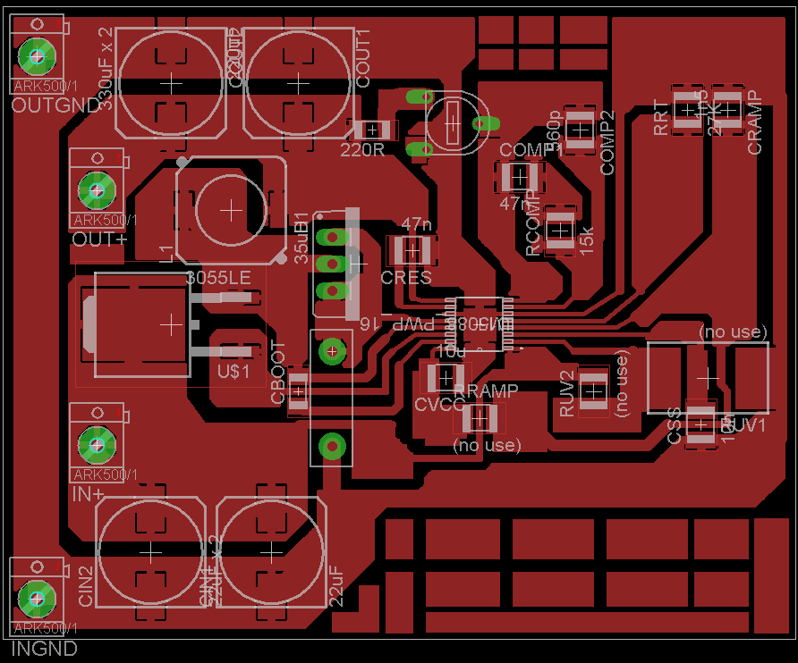
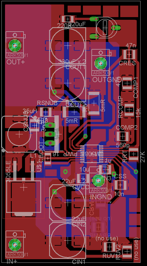
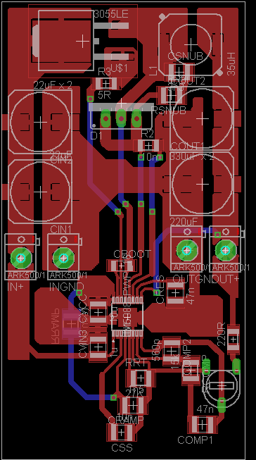
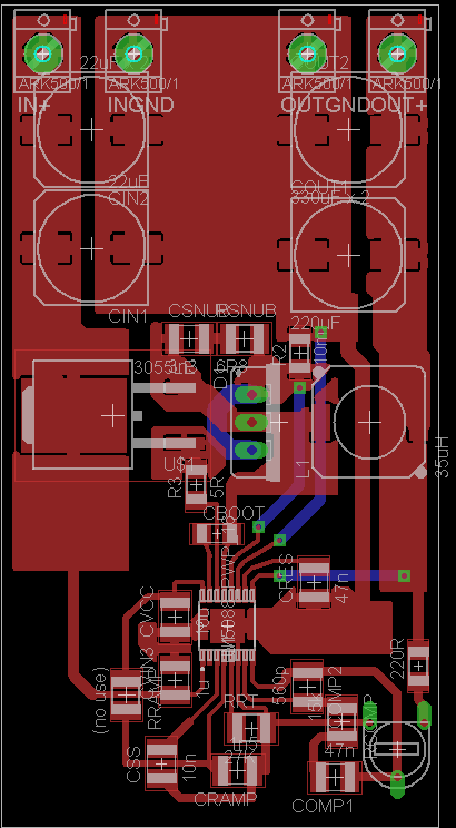
i am learning using buck regulators. I've designed LM5088-2 for input 12V and output 4V (frequency chosen 220kHz). I have problem with finding correct loop compensation. I've chosen 35uH inductor (for low ripple current), 880uF electrolytic output capacitor, measured voltages at SW, FB and RAMP. Is this "pulse skipping" problem of compensation ? (Compensation with Rcomp=15k, Ccomp=47n, Chf=560p) In my case output ripple voltage and transient response isn't much important. How musch is ESR of output capacitor important for correct compensation ?

Many thanks.

Michal 

SW and Vout
  

SW and RAMP
  

SW and FB 
  

  • Hi

    Can you share your schematic and layout for more investigation ?

    Regards,

    Eric

  • Hi, 

    yes. There is schematic:

    and layout:


    Not using UVLO resistors. I have tried some other compensation networks (now R=33k, C=47n and Chf=43p) with similar results. The same kind of problems i had with more buck regulators => i am missing some important fact. 

    Thanks,

    Michal
     

  • Hi Michael

    Please try these items one-by-one. I guess a current sensing noise causes the issue.

    1. Disconnect CSG from the DAP connection and then connect CS and CSG directly to the Rsense using a shielded wire. Ideally CS and CSG should be kelvin connected to the Rsense using short, low inductance paths.

    2. Use R-C filter at CS-CSG, which minimizes inductive noise. Ideally Rsense should be low inductance SMD. 

    3. Place Cvin from #1 pin to #6

    4. Use R-C snubber at switching node.

    4. Decrease Rramp ?

    Regards,

    Eric

  • Hi,

    i've tried, with same results. Rsense is wire-wound resistor in ceramic case. I've made new board layout with low inductance Rsense,  improved ground path and your tips. Do you have any sugestions before i will make it please ?


    thanks

    Michal 

  • Hi

    There should be short direct path from Cin_gnd to Cout_gnd.  The path should not go through the IC ground or go beneath IC.
    Ground connection of the bottom feedback resistor should be connected to the IC ground, not the ground of Cout.
    Use one Rsense to minimize inductance.
    Reserve a foot print for high-side gate resistor
    Cboot should be placed as close to the IC
    Place Cvcc as close to the IC

    By the way, please try again with a high-side gate resistor. If the issue is caused by switching noise related with the layout, you might be able to see an improvement by adding 2~10ohm high-side gate resistor.

    Regards,

    Eric

  • Hi,

    thanks for tips. I've made new layout. Is it better ?

    I've tried high-side gate resistor at old layout with no succes. Old layout was wrong. I did't know how much layout affects performance and i've made it with plenty of place for changing components during tests.


    Thanks for your time

    Michal 

  • Hi


    It is better to enlarge AGND plane in current layout. If possible, please consider flipping power stage area vertically. (See the capture below)

    Regards,


  • Hi,

    thanks. What about this ? 


    regards,

    Michal 

  • Hi

    It looks good except CS-CSG is crossing switching node. I think you can route the two traces beneath VOUT plane which is not switching, is DC voltage, is connecting Cout(+) to Rfb_top.

    Additionally, by moving LM5088 towards 2 o'clock direction, you can have shorter CS-CSG connections.

    Enlarging RRT, Rfb_bot and Css ground is always recommended.

    Regards,

  • Also, you can utilize bottom side of the PCB beneath the LM5088 as a thermal pad.

  • Hi

    thanks for guidance through layout design. I've moved chip upper right and modified traces to sense resistor. What about this ?  


    Thanks.

    Michal 

  • Now it works with efficiency 94% (13V from 24V at Iout 4A) . Thanks for help Eric.