This thread has been locked.

If you have a related question, please click the "Ask a related question" button in the top right corner. The newly created question will be automatically linked to this question.

TPS3813K33

Other Parts Discussed in Thread: TPS3813

Hi,

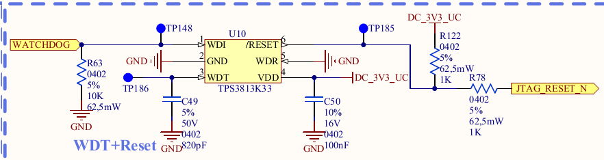
I am facing an issue with a Watchdog/supervisor TPS3813K33.

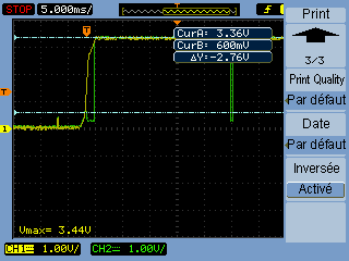
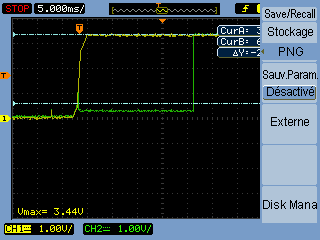
The TPS is resetting the ECU by itself before the first trigger of the WDT pin.

In fact the RESETN pin is not held low for Td timing (25ms low state of RESETN at startup) like in the description, when the VCC is 3.3V, the RESETN is high, and after 25ms, the is a low state of the RESETN pin that make the CPU reset.

Normally, after power on, the refresh frame is inactivated until the first trigger of the WDT pin, so the CPU should not be reset.

Is there someone who have already faced such an issue?

Why the Td time is not respected by the TSP3813K33, is it programmable?

Thanks for you support.

Damien

  • Hi Damien,

    The TPS3813 should operate as shown in the electrical characteristics of the datasheet. Please attach a schecmatic of your design with the TPS3813 and waveforms of your applicaiton issue (VDD, WDI, RESET) so that we can identify possible problems. Thanks!

    Regards,

    Darwin

  • Hello,

    Please find enclosed the detailled description and of signal when it is working and when it is not working as expected.

    There is also the part of schematic related to the TPS.

    Yellow is 3.3V and Green is RESET\ pin of the WD.

    NOK case:

    OK case:

    here is the schematic part of the WD.

    The JTAG_RESET_N is directly connected to the Renesas micro controller.

    Expected window is about 200ms according capacitor value and dispersion.

    Do you see something wrong in how we use the TPS component?

    Thanks for your support.

  • Hi Damien,

    Thank you for sending this. I initially do not see anything wrong with the schematic. For the waveforms, can we look at WDI, VDD, and RESET signals in the same graph for the NOK condition. Thanks!

    Regards,

    Darwin

  • Hello Darwin,

    I have made the measurement for the WDI, the signal is correct, that means that the value is always at 0 until the first rising edge done at 120ms by the CPU software.

    There is no unintentionnal move of the WDI during the power up sequence. (pull-down to GND in the schematic as you can see).

    Do you have an idea on how I could make such screenshot in the NOK case with the TPS chip?

    thanks for your support.

  • Hi Damien,

    Looking at the waveforms again, the device should at least wait 20ms when VCC is nominal. Do you think the load might sometimes be pulling up the output? You may want to try removing the load so that you'll only see the SVS performance.

    Regards,

    Darwin

  • Hello Darwin,

    We try to set a 10K resistor to pull up to VDD instead of 1K, and it seems to work fine.

    Is there a recommendation from TI about the value of this pull-up resistor?

    I cannot find it in the datasheet.

    thanks for your feedback

  • Hi Damien,

    Yes it is not shown in the datasheet but I can recommend one. The electrical characterstics table shows that during power up, it is characterized with 50uA to guarantee 0.2 Max VOL. Therefore, I recommend using the same startup condition and increase your pullup resistor to at least 66.5k (since the pullup voltage is 3.3V).

    Regards,

    Darwin