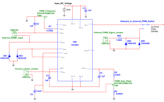
I am using the Texas Instrument UC3824 PWM chip to supply a signal for a Senior class lab PCB. We were troubleshooting the board and were having trouble making the chip supply the correct PWM output. We know that the board is connected correctly because when we apply the 12V Vcc, the PWM signal initially comes through perfectly (Oscilloscope probe at pin 11), but after 10-30 seconds, the signal flickers on the oscilloscope and disappears, leaving voltage spikes only at the points where the PWM signal goes from low to high. If we disconnect the power and reapply it, the signal comes back, but disappears again, usually quicker than before. What we can't explain is that when we probe Pin 4 (Clock), the signal from pin 11 comes back clearly and stays on, but disappears as soon as the probe on pin 4 is removed. Also, the inverting output (Pin 14) always works correctly unless we probe pin 11 and pin 14 simultaneously (both of the chip outputs). So, I am looking for more information on how the UC3824 chip works and perhaps why we are getting this output.
Thanks
Schematic:


