Hi,
My name is Guilherme Muller and I’m developing a step-down SMPS using UCC2893 from Texas. My benchmark is ~90% of efficiency, so I’m using an active clamp forward converter with synchronous rectification, similar to UCC2897A EVM.
This is my first SMPS, so I’m having a lot of troubles and doubts within this project.
Our SMPS is a 60W 5V output, with nominal 125Vdc input. Our temperature rating is 85ºC, so the dissipated thermal energy should be minimum (I’m considering 10W max).
During the validation of the first revision, I got caught in a series of problems within the control loop and other configurations. Adjusting them later, my maximum efficiency today is 82%@100V input, and 78% @ 125V.
I’m working on this product for at least a month trying to raise this efficiency, with no success. I’ve followed to the letter the slua535 (Understanding and Designing an Active Clamp Current Mode Controlled Converter Using the UCC2897A) and found no clue about what is happening.
I´ve already tried a few of solutions, but none helped, cited below.
I’m looking for something I have missed in this project, to find out why our efficiency is so low. I’m trusting on TI Engineers to help me find a solution.
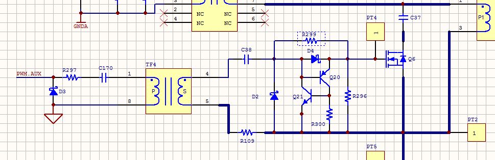
Schematic
The schematic is attached on 01400641.pdf.
The BOM is attached too, although, some components have changed.
Transformer
I’ve analyzed the power transformer in detail, looking for a project error. This transformer is custom made, since our isolation requirements are 3750VAC. The real transformer model is below:
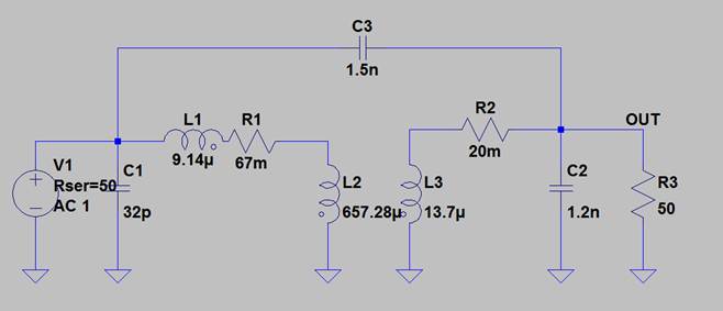
V1 and R3 are test parameters for simulation.
My first assumption was that the secondary series resistance was causing this low efficiency, since the I^2*R power dissipation would be 2,88W at maximum output power (12A). A new transformer was made, with lower series resistance (5mOhms) and no change was noticed.
Reading the slup081, I started to consider the leakage inductance (9.14 uH) as the main problem. So, I’ve changed the transformer just in case and started using the PA0810NL from the EVM. The result is worse (76% eff max and a lot of instability) for now, since I have not changed all the parameters.
Switching Mosfets
Checking the waveforms from the switching FETs, the shape of the gate of the four main FETs seems a little rounded, which could be from a high input current. Although I’ve tried to reduce this value, this was not possible.
The primary FETs are SiHF840LCS-GE3 and the Synchronous Rectifiers are IRFH5302. Their output capacitance, which could result in switching losses, are minimum (170pF for the primary FETs and 860pF for the SR FETs)
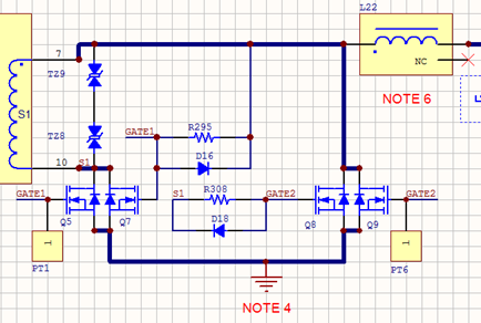
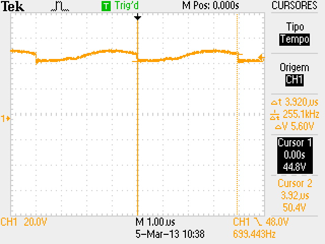
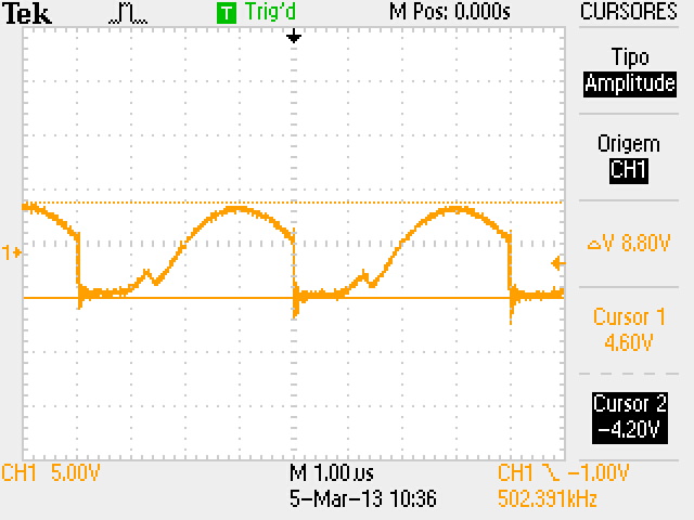
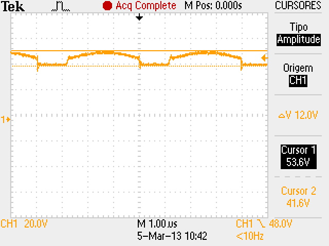
Synchronous Rectifiers and Test Points used
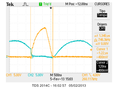
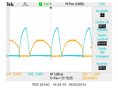
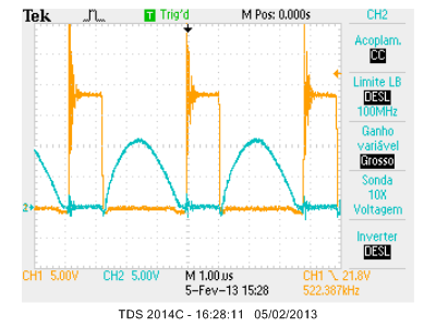
Yellow - PT1, Blue - PT6, 5% Load
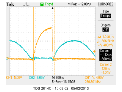
Yellow - PT1, Blue - PT6, 100% Load
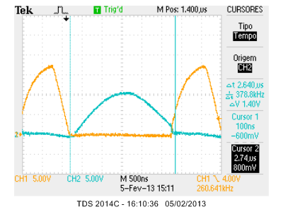
Yellow - PT1, Blue - PT6, 5% Load
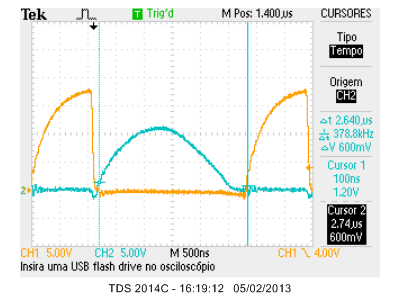
Yellow - PT1, Blue - PT6, 100% Load
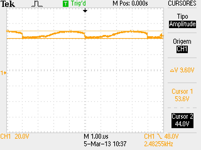
Yellow - Qf (TZ8) VDS, Blue - PT1, 5% Load
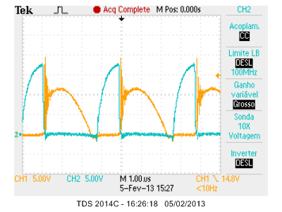
Yellow - Qf (TZ8) VDS, Blue - PT1, 100% Load
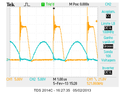
Yellow - QR (TZ9) VDS, Blue - PT6, 5% Load
Yellow - QR (TZ9) VDS, Blue - PT6, 100% Load
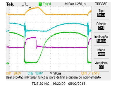
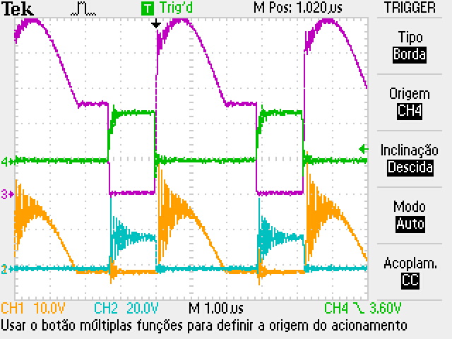
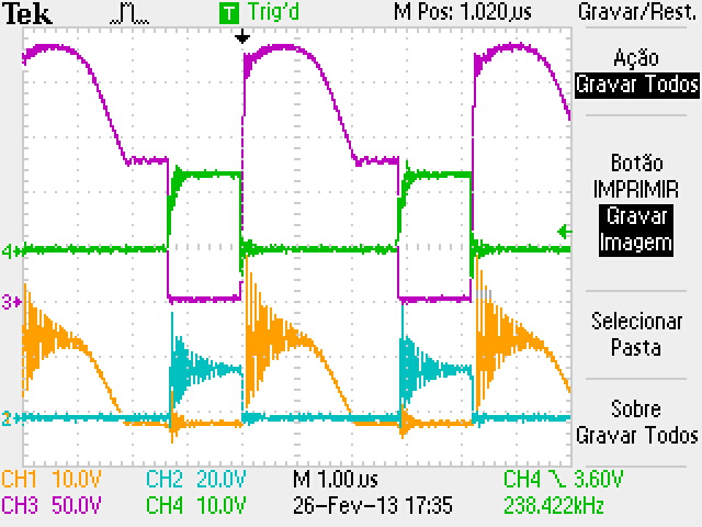
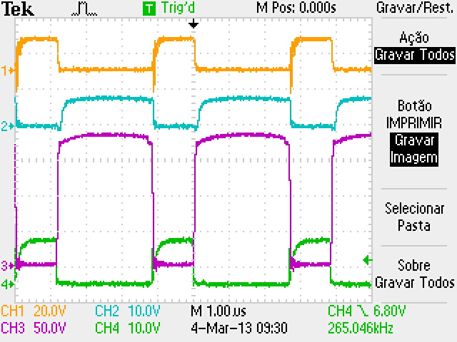
Yellow – PT1
Blue – PT6
Purple – Main FET Gate
Green – Aux FET Gate (clamp)
5% Load
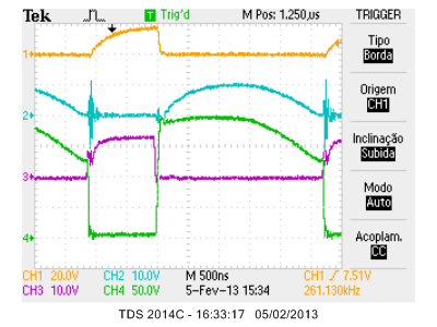
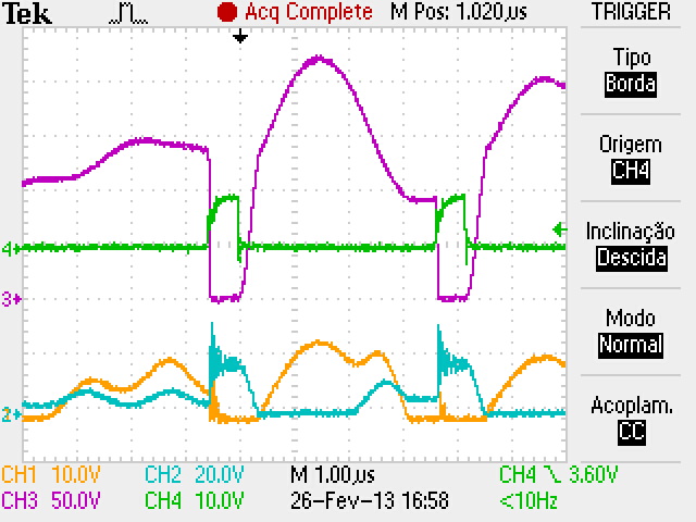
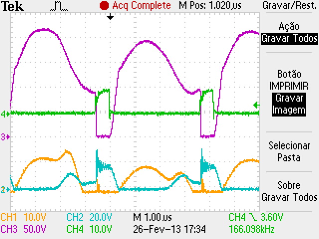
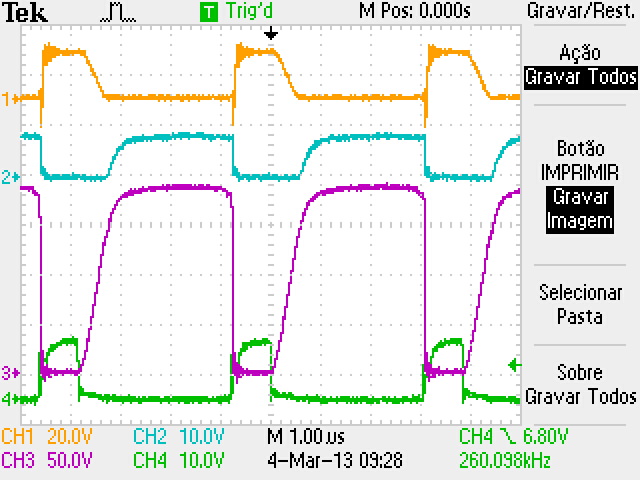
Yellow – PT1
Blue – PT6
Purple – Main FET Gate
Green – Aux FET Gate (clamp)
100% Load
I've already changed and recalculated the whole components lots of times. Also, I experimentally changed them to see the effects. I’m just hoping a tip or a north to my problems.
Thank you very much in advance,
Kindly Regards