This thread has been locked.

If you have a related question, please click the "Ask a related question" button in the top right corner. The newly created question will be automatically linked to this question.

Why the setup converter just reach 100V?

Other Parts Discussed in Thread: LM3488

Hi,

Is there someone can help me find the reason why my 24vdc-150vdc converter just reach 100v.

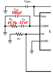
I calculate  a 24V-150V 1.2A converter follow the datasheet of lm3488. The circuit configuration is same with the  figure 18 of the lm3488 datasheet (plus a Rsl resister between pin1 and Rsn. the pin2 was float--- no compensation ). It works at 488Khz, the Rsl =270ohm, Rsen=9mohm, RF1=260Kohm,Rf2=2.18Kohm, l=10uH Ra=30Kohm.

When I change the Rf2, the output voltage did not change. I measure the swtch driver signal, it was just 14--25khz.

Is there someone can tell me what it is problme.

Thank you.


Dison

  • Hello Dison,

    Your circuit seems to be working unstable. Would you please send us your design schematic with component values? 

    Thanks,
    Akshay 

  • Hi Akshay,

    Thanks for your reply.4606.img074.pdf

    The enclosure is my circuit. the Rfa=30Kohm(I forgot put it on the draw).

    I tested the circuit without load. it work at 100VDC very well. But it should go to 150V. I need your help.


    Thanks,


    Dison

  • Hi Akshay,

    I forgot these too.   Rsen=9mohm, Csen = 104K.

    Thanks,


    Dison

  • Hello Dison,

    Here are a few comments/questions about your design:

    1) Your load requirement is 1.2A at possible max duty cycle of 85%. This means that the average FET current would be above 7A. The possible conduction power dissipation through the RdsON would be about 4W and the switching power dissipation would be about 3W. This is a fairly high number. The FET you have chosen has a typical RdsON of 77mOhms and a maxTj of 175degC. From an ambient of 30degC, you could allow 145degs of temp rise before you are in trouble. Therefore you'd need about 20degC/W of thetaJA. In order to achieve this, you will have to use a pretty large thermal heat sink in order to keep the FET from smoking at the high frequency and the high load. I assume you have this in place. The layout for this design would also be critical.

    2) According to my calculations, after giving some padding on the current limit, I get Rsense as 5mohms. I believe the schematic in the datasheet has a small error. The Csen component on your schematic is connected in parallel with Rsen. In practice it should be right between the Isen pin and ground. It is a noise bypass cap and should be very close to the pins. In your earlier post you mentioned you have Csen of 104K. I am not sure what you mean by that.

    3) You have a cap of about 100pF in parallel with the lower feedback resistor. Why do you have that?

    4) You mentioned that the you left comp node floating. May I ask why you did so? According to my calculations, I see that the compensation components required are Rc = 82.5kohms, Cc1 = 1.5nF, and Cc2 = 150pF. Cc1 is in series with Rc. Cc2 is in parallel with the series combination of Rc and Cc1.


    Let me know if this helps.

    Regards,
    Akshay 


  • Hi Akshay,

    Thanks for your reply.

    Let me explain what I think.

    Normally, the  power will supply 10mA to resistive load. Sometimes, it need pulsatingly drive a inductive load( like a coil) in 1.2A current for 1-5s.

    In this time, driver switch will work in 14khz. So I did not pay attention to the power  dissipation. About the Csen, I think you are right.but I did that according to a drawing which is figure 6 of page 12 of lm3488 datasheet. Anyway, I will move it to between pin1 and Rsl and close PIN1. The cap of 100pf also come from the datasheet. it is last line of text in page 17. I think it will be close with FA pin.

    I left the PIN2 float because I read some information some where. I think I should increase them.

    Do you think floating PIN2 is the reason that converter can not reach the 150V  .

    Other, would you tell me how you select the Rsl( because it is 9mohm according to my calculation) and  how you selcet the Rf1 and Rf2 after we get the Rf1/Rf2.

    I will fix  the circuit and test again.

    Thank you very much.


    Dison


  • Hi Dison,

    The datasheet schematic has an error regarding the Csen. It should be close to the Isen pin.The 100pF cap should be close to the FB pin and not the FA pin. If the control loop is not compensated properly then you can have instabilities and that may cause your system to malfunction. That could be a reason you were not able to hit 150V. Please use the values I sent earlier.

    The 5mOhm value was for Rsen and not Rsl. Rsen value is calculated based on the internal sense voltage limit. If you add a little more tolerance to the switch current limit, you'd obtain a lower value for sense resistor. Also make sure that your layout is well optimized. Since you have really large switching currents at full load, any amount of noise will cause an unstable behavior.

    Regards,
    Akshay 

  • Hi Akshay,

    I have completed the testing according to your value, It did not work, the output voltage is 3V. When I just change the 5mohm to 9mohm, the output is 88V.

    Would you give me some advice for that.

    Other, I also build a 24V-150V 150mA convertor which I got the design from WEBENCH Designer tools. it works , but the LM3488 was damaged when I keep it work for about 2 hours with a 18kohm load. So far 2 pcs LM3488 were damaged. Would you help me to find the reason.

    Thanks,

    B.Rs,


    Dison

  • Hello Dison,

    Have you added the compensation components as well? What happens when you use the same Rsns along with the compensation components? Also, please share your other schematic for the design you created on Webench. 

    Thanks,
    Akshay 

  • Hi Akshay,

    Yes, I added  the compensation components, there is litter different.The output slightly bigger.

    The output was 80V without the  compensation components, it was 88V with the  compensation components.

    The enclosure is my 24-150V 150mA power. 1641.it is 150v 150ma power for mid-voltage before spark 2.pdfI choose the D:MUR1520G. Because I want reduce device volume, I change the  L1:AIUR-06-271K and Cout:ECA-2EM470.

    Thanks,


    B.Rs,


    Dison

  • Hello Dison,

    What current are you testing at for your higher current design? Are you seeing lower voltage at no load? Or is it 150V at no load and then drops when you start increasing load? What is the behavior with the 9mOhm resistor and the compensation components?

    I would like to see scope images of the Vout, Vin, Vswitch nodes along with the Inductor current for both your designs. If the layout is not optimized, the resulting noise could cause the controller to fail eventually. Please also send good quality images of your board layout that you have for this design. You could also send Gerbers in addition to this information.

    Regards,
    Akshay

  • Hi Akshay,

    I only tested the higher current converter without load. I will send the wave draw to you later.

    I build both converter  on solding bread board. So I can put every part of circuit far away each other. In fact, the Vout and Vin were more smooth in higher current converter than lower current converter.

    As you know,the  lower converter  is designed by WEBENCH Designer tools and works very well. So  I try to calculate it's every components parameter according to the LM3488 datasheet for checking  the method of calculation in the datasheet. But it did not work. Would you tell me what is different between the method of calculation in the datasheet with the method of calculation of WEBENCH Designer tools. Is  the method of calculation in the datasheet correct? Would you help calculation the lower converter again with detail.

    Thank you very much.


    B.Rs,


    Dison 

  • Hello Dison,

    Bread-boarding a converter is not advised for production purpose. It might be okay for a quick test at low switching frequencies. Keeping all the components far away from each other is a strict violation on a switch regulator layout. Please refer to AN-1204 (http://www.ti.com/lit/an/snva656/snva656.pdf) for a layout example and to AN-1229 (http://www.ti.com/lit/an/snva054b/snva054b.pdf) for a detailed analysis on switching regulator layout.

    This could very well be the problem with your lower current design too. Too much noise in the system can definitely cause the part to fail eventually. There is no big difference between the Webench calculations and the calculations in the datasheet and both are correct. I am also attaching a presentation on EMI in SMPS and ways to mitigate it using good board layout.8228.PCB layout and EMI mitigation.pptx

    Regards,
    Akshay 

  • Hi Akshay,

    Thanks for the data you recommended, That will be very useful for my PCB design.

    Both of the 150V converter works.

    About he 150mA converter, I found the reason that the LM3488 be damaged. Sometimes  a over 7V plus  is on the FB, which come next  stage high voltage plus. When I reduced the trace lengh which connect the FB pin with Rf1 and Rf2, The problem have been solved.I also add a zener diode on FA pin and COMP pin for protect the IC. They bring a slightly increase of  output voltage. In the process of the solution to this problem, I tried to add a zener diode on FB simply, but It will bring a huge periodically spike on Vout.

    Would you help me to analyse why Vout product the huge periodically spike and if  I can remove it by adjust the compensation circuit, and how ?

    About the 1.2A converter, I found the reason that it just output half voltage or lower voltage. It is that  Rf1 and Rf2 is too small which will make the current of FB bigger. I think bigger current of FB will bring bigger error. So the Vout can not reach to 150V. When I changed the Rf1 and Rf2 for keep the FB current to close 15nA which come from datasheet, The converter works. I think this should be primary cause.

    About the Rsen, in face, both of  9mohm and 5mohm  works. When Rsen =5 mohm without Rsl, the converter will supply mor bigger current then Rsen= 9mohm with 270ohm Rsl. The reasen that converter just output 3VDC with Rsen=5mohm is that my 24VDC input was not stong enough. So your calculation is correct.

    About the Csen. I think the drawing of Datasheet is correct. It should parallel with Rf2 before Rsl, because the signal of Pin Isen is current mode which is not easy to be interference and the signal of Rf2 is voltage mode which is easy to interference. So the Csen is for reduce the interference on Rf2.

    About the comp. I found the Vout will be slow move around the 150V (like as it move slowly from 146V to 150v and then slowly move back ) without compensating circuit. Both compensating circuit works, which you select fc =804Hz,fzc= 526Hz, Cc1=1.5nF,Rc=82.5kohm Cc2=150pF and I select fc=69kHz, fzc=9.96kHz, fpc=1.28khz, Cc1=2.28nF, Rc=7Khz. I have read the  "AN-1994 Modeing and Design of Current Mode Control Boost Converters". I think the open loop transfer function of main circuit should be  equation 30 in page 5 and the open loop transfer function of  compensating circuit should be equation 32 in page 6. But I can not found the close loop transfer function of the converter system. I am not very clear about the whole calculation. For example, How did you calculate the Cc2, and How did you remove the Zero of main transfer function  by select poles of compensating circuit(like as the 66khz zero of right half plane in page 7).

    So would you recommend some application notes or artical to me ? Would you like send your calculation process with detail to me?

    Thank you very much.


    B.Rs,


    Dison


  • Hello Dison,

    Give me a few days and then I will reply to this. I have been caught up in some urgent work.

    Regards,
    Akshay 

  • Hello Akshay,

    Ok, no problem.

    Thank you very much.

    B.Rs,

    Dison 

  • Hi Akshay,

    Did you completed the urgent work?

    I have a question about the LM 3488.The FA or FB or DR short to GND, if cause a huge current on Vin pin which will damage the Vin area.

    When my 150V 150mA power supply work in strong pulse interference environment, the lm3488 was demaged few times. Because sometimes there is bigger pulse on FA, FB and DR pin, I want simply clampe the voltage of these pin for keeping their voltage under 7V  by Tvs or zener device. But the Vin area became very heat and  was burned. Because the power suply works very well without a strong external interference, I am sure that the cause of the LM3488 damage did not come from inside of the power supply. Damage is described below:

    1.  Without any protect, Vin area was bruned with fire Vin area.(I think somewhere was breakdown of IC. The Vin area was burned by a bigger current)

    2. Without any protect, IC did not work without obvious phenomenon (I think a pin was damaged by a over voltage pulse).

    2. Protected by zener device on FA,FB, and Vin, It work for longer time. Then the zener on FA was breakdown power supply still work fine.Finally the IC did nit work without obvious phenomenon.(I think the Vin area was burned by a bigger current )

    3. Protected by TVS device on FA,FB,DR and Vin. the Vin area was burned with smoke on Vin area.(I think the Vin area was burned by a bigger current )


    Would you give me a recommended PCB layout and some  recommended  guard method for against the strong pulse interference environment .


    Thanks,


    B.Rs,


    Dison


  • Hello Dison,

    Unfortunately I am not yet free and have a long term project going on. I had earlier sent you an extensive presentation on EMI and mitigation techniques using good layout practices. Have you gone through that? 

    I have also forwarded your query to a colleague. I will ask him if he can support your query. I apologize for the delay in getting back to you.

    Regards,
    Akshay 

  • Hello Dison,

    could you please share your schematic? I would like to review it before to say anything.

    Regards,

    Giuseppe

  • Hello Giuseppe,

    Thanks your replay.

    I design the  0.15mA 24v-150v convertor base on Lm3488 by the WEBENCH® Designer.(INPUT Vmin=18,Vmax=32v; OUTPUT Vout =150V ,Iout=0.15, then select single out, select lm3488 design ) It's SCH was not changed.There are fews part I have changed. They are:D1 =MURS360T3,L1=SRR1260-271K. I built it on a breadboard.  It works very well in normal environment.

    When it work in strong pulse interference environment, the lm3488 was demaged few times. Because sometimes there is bigger pulse on FA, FB and DR pin, I want simply clampe the voltage of these pin for keeping their voltage under 7V  by Tvs or zener device. But the Vin area became very heat and  was burned. Because the power suply works very well without a strong external interference, I am sure that the cause of the LM3488 damage did not come from inside of the power supply. Damage is described below:

    1.  Without any protect, Vin area was bruned with fire Vin area.(I think somewhere was breakdown of IC. The Vin area was burned by a bigger current)

    2. Without any protect, IC did not work without obvious phenomenon (I think a pin was damaged by a over voltage pulse).

    2. Protected by zener device on FA,FB, and Vin, It work for longer time. Then the zener on FA was breakdown power supply still work fine.Finally the IC did nit work without obvious phenomenon.(I think the Vin area was burned by a bigger current )

    3. Protected by TVS device on FA,FB,DR and Vin. the Vin area was burned with smoke on Vin area.(I think the Vin area was burned by a bigger current )

    Would you give me a recommended PCB layout and some  recommended  guard method for against the strong pulse interference environment .

    Thanks,

    B.Rs,

    Dison


  • Hi Akshay,

    Ok.

    Thanks.

    B.Rs,

    Dison

  • Hello Dison,

    I took a look at your schematic and I have few suggetions.

    I am assuming:

    VIN = 24V

    VOUT = 150V@1.2A

    1. Move Csen between ISEN and GND. 

    2. Comp pin cannot be floating, compensation is needed not only for stability but also for DC error, please use the following compensation network:

    3. Change the feedback resistor value to Rf2 = 1kOhm and Rf1 = 118kOhm. With a too high feedback resistor value there can be issues due to non ideal internal error amplifier.

    4. Change sensing resistor value Rsen = 5mOhm.

    5. Change Rsl = 499 Ohm.

    6. Remove the capacitor in parallel with Rf2.

    7. Finally please make sure that all your power stage components are rated for the correct amount of current and voltage.

    If with all those changes your design still does not work then I would like to take a look at your PCB layout.

    Regards,

    Giuseppe

  • Hi Giuseppe,

    Thanks your reply. Sorry,I didn't make it clear.

    I designed two power convertor: One of them is 24-150v 0.15A and other one is 24-150V 1.2A. Their SCH are same with difference parts. They all works now. 

    My question that I described last email is about the 0.15A convertor. Because It is enough for my apply.

    Would you help me to find the reason about that.

    Thank you very much.


    B.Rs,


    Dison


  • Hello Dison,

    Using a breadboard is not very suitable when it comes to power circuits therefore i really suggest you to make a PCB layout.

    Also let me give you some advices when you create the layout.

    1. The most important layout rule is to keep the AC current loops as small as possible. In a BOOST regulator the primary switching loop consists of the output capacitor, diode, MOSFET and sensing resistor. Minimizing the area of this loop reduces the stray inductances and minimizes noise and possible erratic operation.

    2. The current sensing circuit in current mode devices can be easily effected by switching noise. This noise can cause duty cycle jitter which leads to increased spectral noise. The sensing resistor should be connected to the ISEN pin with a separate trace made as short as possible. Route this trace away from the inductor and the switch node. For the voltage loop, keep the feedback resistors close to the IC and run a trace as close as possible to the positive side of the output capacitor. As with the ISEN line, the FB line should be routed away from the inductor and the switch node. These measures minimize the length of high impedance lines and reduce noise pickup.

    3. A ground plane in the printed circuit board is recommended as a means to connect the quiet end (input voltage ground side) of the input filter capacitor to the output filter capacitors and the PGND pin of the controller. Connect all the low power ground connections directly to the regulator AGND. Connect the AGND and PGND pins together through a copper area covering the entire underside of the device. Place several vias in this underside copper area to ground plane. If a via is needed to connect the sensing resistor to the ISEN pin, then place that via in the inner side of the sensing resistor such that no current flow occurs. Place several vias from the ground side of the output capacitor(s) to ground place, that will minimize the path for AC current. The PGND and AGND pins have to be connected to the same ground very close to the IC. To avoid ground loop currents attach all the grounds of the system only at one point. A general rule of thumb is to maximize the low impedance area (VIN,VOUT, GND).

    4. Use thicker traces for the gate signal from the DR pin to the gate of the MOSFET.

    Furthermore, could you please share your final design where VIN = 24V and VOUT=150V@150mA? I would like to review it.

    Regards,

    Giuseppe