This thread has been locked.

If you have a related question, please click the "Ask a related question" button in the top right corner. The newly created question will be automatically linked to this question.

LMR62421XMFE - problems with external components connection

Dear Sir/Madam,


We are planning to use LMR62421XMFE chip in our design and made prototype PCBs.

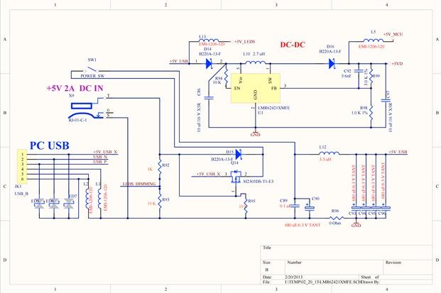
Please see attached fragment of the SCH diagram.  The input  voltage is from 4.5V with 4.9V, the output voltage is 5V and current is 1.5A.

It is based on WEBENCH.

Could you please check and let us know what is wrong with the SCH?

After adding   C92 5.6nF we measured the voltage 5.6V on net +5VD and voltage 5.66V on net +5V_MCU and also could hear high frequency noise.

 After removing C92, the unit is working properly without any high-frequency noise, and measured voltages are below:

a)      net +5VD = 4.99v

b)      net +5V_MCU  =5.02V

At the same time according to data sheet the SCH requires to add C92.

Please comment.

SCH is attached.

  • Hello Leonid,

    C92 or Cff (feedforward capacitor) as it is generally called is not always needed. The addition of Cff creates a zero at Rfbtop x Cff and a pole at (Rfbtop || Rfbbot) x Cff. This means that if not properly calculated, it might not be doing any good for the system. If you are hearing noise that means there are instabilities and ringing in the audible frequency range. It would be interesting to see a scope image of the swtich node voltage. If there are instabilities, then you will not see a stable square wave.

    How much voltage is your output cap rated for? If you are using a 6.3V cap for a 5V output, then you might not have any capacitance left. Reduced capacitance causes the bandwidth (crossover frequency) to slide to a higher value and it might cause the phase margin to reduce. If you have a frequency analyzer, you could plot the bode plot of the system with the Cff on and off. You could also use Webench to simulate the effects of reduced Cout. To remove Cff from the circuit, you could reduce the value to some femto farads.

    If you are obtaining a clean Vout and the switch node voltage looks stable without Cff, then you do not need to add that in. It is not a mandatory component. But I would suggest inspecting the various nodes on the circuit and ensuring stability. I hope this helps.

    Regards,
    Akshay