This thread has been locked.

If you have a related question, please click the "Ask a related question" button in the top right corner. The newly created question will be automatically linked to this question.

UCC28950 / Position of current transformer

Other Parts Discussed in Thread: UCC28950

Hi,

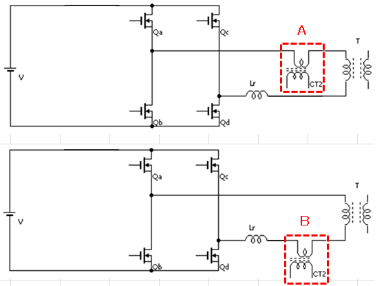
Our customer is now evaluating UCC28950 and now they try to move the current position. They moved CT to near primary side of transformer like attached but they can not confirm the same operation compared with original position. They tried to move it because they found that the vwaveform at CS pin was cleaned off.

Best Regards,

Sonoki / Japan Disty

UCC28950 Position of current transformer.pdf
  • Hello Sonoki,

    If you move the CT theer you will need bridge rectifier for the CS.

    Regards,

  • Hi Mike-san,

    I'm sorry that I commented wrong information in attachment. Please see revised one. They already added bridge rectifier as attached schematic. Is this configuration incorrect?

    Best Regards,

    Sonoki

    UCC28950 Position of current transformer_2.pdf
  • The bridge rectifier CT output seems O.K.  I would put the CT current senseing winding on the other side of the transformer.   You also should add clamping diodes between the Lr and transformer connection.  This will prevent the secondary rectifier's frome getting damaged voltage spikes caused by the differencs in Lr and T primary current.  Please refer to the application note  for diode placement.  http://www.ti.com/litv/pdf/slua560c  These differences in current may also explain why the CT was not working correctly.

    Regards,


  • Hi Mike-san,

    Sorry for may delayed response. Please let me start new post and additional information for this thread.

    Best Regards,

    Sonoki

  • Hello Mike-san,

    I am Sonoki's colleague and I want to ask about position of CT current sensing winding.

    (1) Which position do you recommend, A or B? (Is there any recommendations?)


    (2) Is there any reference design under this CT position?

    Typical application(datasheet p.1) shows CT is connected to the top of the full bridge, but my customer wants to put CT winding at this position.   

    http://www.ti.com/lit/ds/slusa16b/slusa16b.pdf

    Regards,

    Yaita

  • Is there any difference between A and B?

    I found your comment below, but I can't understand the meaning.

    "I would put the CT current sensing winding on the other side of the transformer"

    Is it my misunderstanding?

    Regards,

    Yaita

  • I think is not a good idea to put the CT in series with the primary of the main transformer.

    The high dV/dt will cause high peak currents through the capacitance of the transformer.

  • I think it is not a good idea to put the CT in series with the primary of the main transformer.

    The high dV/dt will cause high peak currents through the capacitance of the transformer.

  • I agree. The best place to put the CT is that used in the UCC28950 EVM - ( TI document sluu421a - sketched below ). Positions A and B are both bad choices and I would discourage putting the CT in either of them.

    There are three reasons for this -

    First. In the positions A and B shown earlier - there is a high dv/dt from primary to secondary of the transformer. This will drive currents across the capacitance from primary to secondary and so cause spikes on the CT output waveform. Spikes in the CT output waveform can cause unstable circuit operation. Additional filtering will be needed to attenuate them but too much filtering can attenuate the wanted current signal. If the transformer is in the position C (below) there is no dv/dv across the transformer so no currents through the primary to secondary capacitance.

    Second: In the positions A and B, a proportion of the discharge currents which flow during the ZVS transitions (as the bridge is going from one switching state to another) will flow in the CT primary and cause additional interference on the CT output signal. These are the currents which charge and discharge the stray capacitance at the switched nodes. These currents do not flow in the CT if it is in position C.

    Third: If the CT is in position A or B it takes up PCB space that is better used to reduce the size of the switching loops around the bridge circuit. Smaller loops will give rise to cleaner switching waveforms and lower device stresses (peak voltage stress). Smaller loops will also cause less radiated and conducted EMI.

    Regards

    Colin

  • The only problem of position C is that the time to reset the transformer is critical. If the duty cycle is near 100% and the current transformer has too much parassitic capacitance, reset of the magnetizing current may be difficult. This is one reason why people has the temptation to put the CT in position A or B.

    If we put TWO transformers, one of each drain of Qa and Qc, we have a full half period to reset the transformer, so any CT will work with a duty cycle close to 100%.

    I tried this and it seems that it works. Your comments will be appreciated.

  • Yes, I've seen this done and it works. The disadvantage of course is the cost of two current sensing transformers.