This thread has been locked.

If you have a related question, please click the "Ask a related question" button in the top right corner. The newly created question will be automatically linked to this question.

TPS61131 SEPIC output problem

Other Parts Discussed in Thread: TPS61131

I'm using the TPS61131 in one of my designs and a I have a problem. I have the LDO running correctly and I have the 3.3V on the output as I want. But, in the sepic output I only have an output voltage of ~1.6V and with no load on the output of the sepic I have a constant ~160mA drawn of the source. 

I already check every aspect of the schematic with the one on the datasheet and it should work. The TPS61131 circuit is completely isolated from the rest of the the design (just started testing). 

Although, there is one thing that I not sure, for this sepic to work do I have to use a coupled inductors, or the individual inductors will do? On the reference designs I see coupled inductors, but on the recommended inductors there are both, coupled and individual...

I can retrieve some plots from an oscilloscope if it helps...

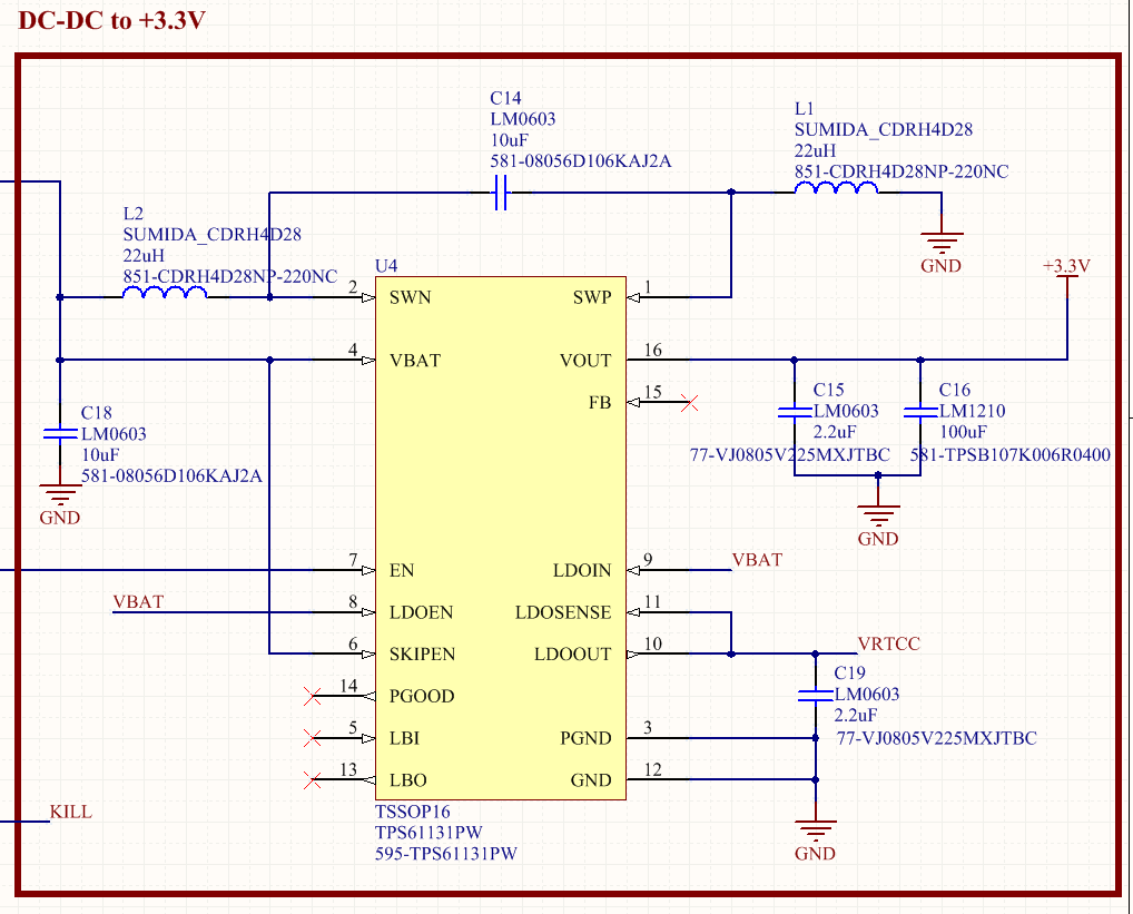
Here is the schematic, I have ~4V on the VBAT pin and also on the VBAT net, and the enable is tied to the VBAT net for testing purposes. 

Thank You!!!

  • Hi Luis.

    It's been a while since I looked a sepic , but from what I remember you can use coupled or individual inductors. If they are individual though the calculated inductance is doubled. If coupled inductors are used , make sure the phasing is correct.

    Cheers

    Robin

  • I'm not sure that practically speaking a SEPIC is the best way to go for these applications these days.  Have you look at our TPS630xx series buck boost converters?

    Yes, you can use separate inductors.  You will need to work with your local FAE to debug the circuit by comparing the waveforms at various nodes to what is expected at those nodes.  You might also order the EVM and test it.  I recommend removing all loads and retesting your circuit.