This thread has been locked.

If you have a related question, please click the "Ask a related question" button in the top right corner. The newly created question will be automatically linked to this question.

Reducing TPS40210 Temperature

Other Parts Discussed in Thread: TPS40210, UC3845

Hi All,

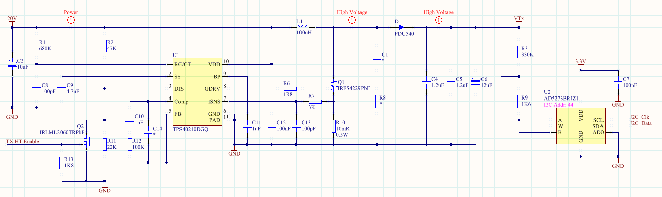
I have a TPS40210 design boosting from 20V up to 120V. When running, the controller IC temperature is around 80 degC, the inductor and FET are around 45 deg C (Ambient is about 20 deg C).

Although 80 in spec for the controller, we need to run the circuit at an ambient of 60 deg C, which may push the IC temperature towards its limit. Are there any non-mechanical (ie. not heatsinks) tricks or circuit alterations that can be used to reduce the IC's running temperature?

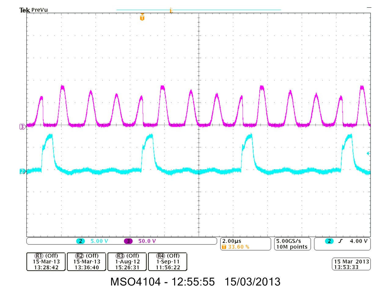
Switching freq: 240kHz
Inductor size: 100uH
Output current: 100mA

Many thanks

Andy

  • Hi Andrew,

    The majority of the losses in the IC are gate drive losses. Two recommendations to reduce the temperature are below.

    1. Make sure the thermal pad is soldered down properly with the recommended footprint and vias given in the datasheet. Also use as much PCB area as possible and connect this to the thermal pad to aid with heat sinking.
    2. Lower the switching frequency to reduce the average gate drive current needed for driving the FET reducing power loss in the gate drive.

    I hope you find this helpful and please let me know if you have any more questions.

    Best Regards,
    Anthony

  • Hi,

    additionally, you can try to put a bigger value for R6, the gate resistor. Try with 10Ohm. The result should be to get the IC cooler and the FET hotter.

  • Hi Anthony and Avi,

    Many thanks for your suggestions. I've given them both a try today and managed a good 15 degC drop in temp. I changed the gate resistor to 10R and reduced the switching frequency. I'd still like the temp lower, but I think I'm at the limits of what I can achieve with these two fixes. Out of interest, from experience would you consider the TPS40210 a chip that naturally runs quite warm?

    With regards the thermal pad. The land around the IC is very limited, but the thermal pad is via'd down to large ground planes. The bottom of these vias also butt up against a metal block.

    Thanks again for your input

    Andy

  • Hi Andy,

    Glad to help.

    In general wide VIN controllers can run hot. The main reason is, for the gate drive voltage an internal LDO is used. This is the source of most the power dissipated by the IC. For higher switching frequencies and for FETs with higher gate charge more gate drive current is needed increasing the power loss. The average gate drive current is estimated by Idrive = fsw * Qg and the power loss is Pgdrive = Idrive * Vin.

    There are some tricks around this which can be used, such as using an external power supply to bypass the internal LDO.

    Best Regards,
    Anthony

  • Hi Andrew.

    The gate resistor is your friend! .  It not only lowers losses, but reduces EMI.  The advice you have is right on the money.  

    I've built a more conventional booster using a GA3460 transformer (Coilcraft) as an auto transformer so I can get 240v 1A pulsed  from 12V (20A pulsed) , this used a UC3845 , 5ohm gate resistor and an IFR3607. This fits in a match box (apart from the input filter caps!) .... and  the driver is cold, the MOSFET is lukewarm, the transformer is very warm to hot., the capacitors are warm, So I'm happy with that loss distribution.

    I've always found that lowering the frequency and increasing the gate drive generally gives you a better result. The marketing types like to push really high frequency components that fit on a fingernail, but you get twice the heat in half the space.

    Some other suggestions :

    • Consider a 1:1 transformer , these are quite common and can be bifilar wound with incredibly low leakage inductance. This will halve the Vds, and at the same time halve the dV/dT across the Miller capacitance that the gate drivers are pushing against.
    • Check for ringing on the drain, (again the gate drivers have to push against this ringing due to Miller capacitance)
    • At 250Khz and 100uH,  the stray capacitance of your coil will be working against you , you might consider a semi resonant voltage doubling configuration so the capacitance works for you, also enables a lower inductance. But that might be a longer path you don't want to go down right now.
    • Consider a MOSFET with a higher on resistance, this usually lowers the gate charge (and gate drive losses)
    • Think about the threshold voltage of the MOSFET (you probably don't get much choice with a 200v MOSFET) , but avoid using a logic level MOSFET when you have 12v gate drive available, this leads to really asymettric rise/ fall times  and gate drive and host of other little problems.
    • You could always use one of those little emitter follower drivers (the NPN/PNP pair in a SOT23) , then it can get hot instead.
  • Hi Bob,

    Many thanks, there's some great ideas there.

    I'm wondering if the inductor's stray capacitance is the cause of a ringing I'm seeing on the switch node (the junction of the FET, indcutor and diode). When the FET switches off, I see the expected voltage boost from the inductor, this then returns to zero, but then I see similar pulses bit later on. Image attached below (FET gate in cyan, switching node in magenta).

    Is there a rule of thumb with regards to inductor calue and stray capacitance; something like, large inductance, more windings, more capacitance??

    Thanks

    Andy

  • Hi Andy, 

    I would start by recommending a  great book "Power sources and supplies, world class designs" by Marty Brown.

    ISBN 9780750686266  , probably the best book in my library of 200+ books.

    There's also some good online design calculators over at coil-craft too.

    And on this TI site there is an AN on boost converters, which is an excellent read , but brushes over inductors , but does mention the heating effect of AC voltage that is ignored by many manufacturers.

    I'm assuming you are proficient at basic circuit design and how an inductor works in theory, and are just hoping for an insight, so you can learn from my decades of mistakes. 

    --------------------- volt / seconds ----------- 

    One really needs to get their head around this, so much of Inductor and Transformer design focuses on currents.  At first glance an inductor is a constant current source so the voltage can really bounce all over the place and not change the current much. Inductors are spec'd by saturation current, but one has to ask how an inductor that supposedly runs at 2A on paper, gets to 10A in the real world and saturates.  Volt-seconds measure the "size" of a transformer/inductor , in the same way a 2 gal bucket holds no more than 2gals; you can point a fire hose at the bucket and you won't get any more into it.  You can get more volt-secs by adding more turns, so sometimes it is convenient to think of the size in volts per turn per hertz.  So for example a typical 30mm to 40mm E core ferrite transformer would be happy at 2 to 5volts per turn at 40-100kHz. Those little 1/2" gate driver transformers are ~ 100v-uS.  Knowing the V-uS limit of your wound component tells you how much headroom you have. So let's look at a circuit a bit like yours. First you apply 10v to the inductor for 10us  (the bucket is half full at 100v.uS) , then switch off, the inductor voltage bounces up to 100V (the bucket drains very quickly), 1uS later, the bucket is empty, the flow stops, the inductor voltage collapses, there is a dead time maybe 1uS and the cycle starts again. 

    • Core heating is caused by dV/dt , this is potentially an issue with high boost designs, as you tend to use only a  few turns to get low inductance to get a lot of current into the coil, but when it flys back you get a really high volts per turn.  If you wanted to optimise a high boost design, you might work backwards from a core loss budget.
    • Core loss goes up dramatically with ringing, so check your circuit over all duty cycles and supply volts as the worst case may not be full load.
    • Increasing frequency lowers the power throughput (as the average current is less)  while raising core loss ; But this can be offsetted with an E type core, you can increase the airgap to increase magnetising current, and reduce core loss.
    • If you don't have much volt-sec headroom and you have reasonable core loss then using a higher frequency with a smaller coil is unlikely to work in spite of the datasheet claims.
    • Cores aren't created equal! Toriodal cores (generally designed as DC filters) can have high core losses when >100v AC is applied above ~40kHz (in a filter application they only have a few volts across them . Core loss of your average E cores above 200kHz dominates  , while below 50kHz  you run out of volts-secs before the core gets warm. The huge air gap of bobbin cores precludes volt-sec issues, but the cores can get hot at high voltage/hi frequency, and they spray EMI. Cup cores are generally made of good ferrite, with a generous airgap, so are good all round, and they are popular in SMD 
    • If you have coil that is limited to say 100v-us at 100kHz  (eg a 20v square wave ), and you want to lower the frequency to half , then you need to double the number of turns, so 4 times the inductance, this gives half the magnetising current, and halves the power.
    • If your MOSFET driver works in "current mode" then it will automatically back off when you hit the volt-second limit, which is why they are so popular.
    --------------- copper loss proportional to RMS current------
    This bit is easy: Unless  operating in CCM with a low ripple or using as a DC choke, the copper losses are generally small in a plain inductor.  
    More difficult with a transformer, as you only get half the space for each winding, and due to transformer action you can have massive ampere-turns in each winding that cancel out, so copper loss can be significant.
    OK I haven't really answered your questions yet, stay tuned....
  • Ok , Back to your questions.

    There are several figures of merit for coils.

    Notably the "Q" and the "resonant frequency"  

    The Q is size invariant , for an airwound coil, the optimum Q occurs when the diameter equals the length. This could be a 10mm diameter single turn from a strip of copper 10mm wide x 1mm thick or 10 turns of 1mm wire , (the latter has 100 times the inductance.) 

    Alternatively, take a 100g spool of copper wire, and wrap it around a 100m long former, 100mm wide , you get the same Q irrespective of the gauge of wire. (10 turns is 207uH

    To a first approximation the inductance increases faster than coil diameter , whereas the capacitance goes up directly  with circumference (if you don't change the gauge) So double the diameter  L = 207uH goes to 562uH  , and resonant frequency  is  more than halved (sqrt(1/LC) ) .  Make the coil 200mm long, and L=414uH but the capacitance drops too.  

    • reducing wire gauge of a coil , or increase in wire spacing lowers C , but not L
    • solenoid coils made from stacked pancake coils  have the lowest capacitance (The Marconi spark transmitter used these)
    • adding a  ferrite core increases L markedly but no effect on C
    • so bigger coils = more L and more C
    • but generally for the same inductance, you would reduce the number of turns as the coil got bigger, (you get more volt seconds with bigger cores, so can use less turns) so a larger inductance , with the same uH would probably be similar capacitance. If you used the same wire gauge, with fewer turns and larger spacing, then C might actually go down with larger coils.  The tradeoff is that you could have lowered the coil resistance by using a thicker gauge , instead of getting less capacitance.
    So a 1turn , 1mm diameter coil resonates ~ 100gHz ,  wrap a one turn wire around the equator and it's 8Hz, so yes size does matter.
    --------- Back to your waveforms ----------------------------
    Yep your coil resonates at 680kHz , probably reasonable for the inductance value used. 
    But your coil must resonate somewhere, so the "ringing" will never go away. 
    It's an entirely normal kind of waveform for a boost converter running DCM at very light load. You will get a nicer looking waveform when it loads up.
    If you could reduce the capacitance, then you would just get more ringing cycles, which just heats up the core.
    If your system always runs at the same power level , then you can tweak the frequency so it switches on when the source waveform is close to ground and get ZVS to lower losses. 
    I wouldn't normally tag your waveform as "ringing" it's just the coil flopping around and harmless. But you can get parasitic ringing when the MOSFET switches off , however your snubbers and slewrate control have eliminated this . This parasitic ringing can be a problem as it is a much higher frequency, generally radiates EMI, and can overvolt the MOSFET and rectifiers. You might see some of this parasitic ringing if the booster transitions to CCM at full load. The cause is usually charge storage in a rectifier diode changing to Schottky or  "soft recovery" diodes helps too.
    If you find you are a long way from CCM at full load , then you might consider a smaller inductor.
    ----------------- current sensor -------------------
    It's useful to be able to measure current on PCB tracks etc with this kind of design work.
    A simple one  to build is as follows: Take a 100uH 0805 SMD inductor ,  now get a  piece of RG58 coax with a  BNC at one end, strip back a few mm at the other end and solder the 0805 inductor on,  and put some heatshrink over it.  Set your scope to 50ohm input and mV range, and there's a current sensor that works from 80kHz up , (if you load it up with a 10ohm resistor it will work down to ~20kHz).  The waveform will be a bit distorted , but you can see current spikes at turnon and off if they are there.
    You will get a better waveform using a 1mH bobbin inductor, but the magnetic field is aligned somewhat awkwardly to use as probe. 
  • Hi Bob,

    Many thanks for taking the time to reply with all this info.

    For my application, the converter is well into DCM even at full load. (I was a bit over enthusastic when stating the load at 100mA, it is more like 10mA). I did have a try at tuning the switching freq to align the FET turn on with a period when the switching node is at 0V, I need to play with this some more. It's a bit of a juggle because the duty cycle obviously changes with frequency!

    I'm also going to try an alterantive FET with a lower gate charge. IRFS4260 rather than IRFS4229.

    I've just ordered a copy of the book you suggested. After a quick preview on Google Books, it looks like a good read.

    I'm going to print out your replies and give them another read through!

    Thanks again

    Andy