This thread has been locked.

If you have a related question, please click the "Ask a related question" button in the top right corner. The newly created question will be automatically linked to this question.

[LM1117] Power supply: Overload problem and the Regulators gets more heat.Give me the best suggestions to solve this problem.

Other Parts Discussed in Thread: LM1117

HI,
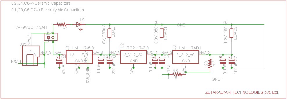
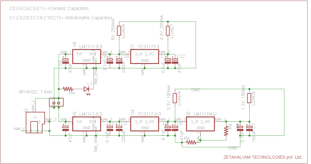
We are using 1.2V,3.3V and 5V and the load consumes 750mA current with the input DC at 7.5V,7AH battery / 9v, 1A from adapter. We are using LM1117(800mA) regulators for this.But we have a problem in this design.We are facing a overload problem and also the regulators gets more heat.So please give me the suggestions to solve this problem .I have attached our power supply schematic diagram (two files,we are tried both the types).

Best Regards,

Naveen

  • Naveen,

    The power lost in the 5V regulator(s) is (Vi-Vo) * IOUT = 3.0 watts.
    The power lost in the 3.3V regulator(s) is (Vi-Vo) * IOUT = 0.68 watts.
    The power lost in the 1.2V regulator is (Vi-Vo) * IOUT = 0.32 watts.

    The circuit board / heat sink needs to absorb heat from regulators and pass that heat to the environment.
    Better heat sinking or changing the design to switching regulators will lower the device temperature.

  • Hi Ron Michallick,

    Thanks for your valuable inputs, Appreciate your suggestion.  Suggest me the required regulators(either linear or switching type). Previously, I mentioned our requirement as shown in schematic diagram. We are using 7.5V,7AH battery or 9V,1A adapter alternatively as a input.We need 5V,3.3V,1.2V output voltage for a 800mA to a max of 1000mA load. So please suggest me which type of regulator is better for our application with their part number to solve the problem. Then we can replace our old design.   

    Regards,

    Naveen

  • Naveen,

    The Webench designer availible on the www.ti.com web site home page (and under power management section) is a powerful tool to select switching regulators complete with recommended circuit components. It gives many choices of various BOM cost and power efficiencies.

    Just enter min/max VIN, VOUT, IOUT and TA temperature then click start design. After a minute solutions will be shown.

  • Please notice that it is not only an issue of converter heating, using linear converters for your battery operated solution is providing a very low efficiency and I would say that it is totally unacceptable.

    For a battery powered solution where you need high current and where the difference between provided voltage and target voltage is high you must consider one of two alternatives

    1 Changing the batteries so they will be as close as possible to the needed voltages, or

    2 Use switching power supplies

    Best regards,

    Avi

  • Thanks Avi,Iam planning to go for switching regulators and also i will choose it in TI Webench designer. If you have any sujjestions for choose switching regulator please sujjest me. 

    Regards,

    Naveen

  • Hi,

    It is really a difficult question to answer, there are many possibilities, and it depends on your priorities (lower cost/ higher efficiency / use devices that you already use in other boards, etc.).

    The best for you is to use Webench, and if after using it your are still unsure about an option, you can post your question here.

    All the best

    Avi

  • Hi Avi,

    Thanks for your suggestion.I will do this by using Webench.

  • Ron Michallick,

    Thanks for your suggestion.I am planning to go for switching regulator by using Webench designer.But i have little bit confusion while choosing output current ratting of the regulator (means doubt to choose Load current). Because presently we need approximately 1A load current,but now am planning to choose it for 3A rated output current regulator,I thought it will helpful for us if we adding other extra peripherals to this in future.But we not sure that the extra peripherals to be add or not,if we add we don't know about how much current its need.I have some doubt here:

    1)Is there any problem to regulators or our peripherals(device), because regulator output current is 3A but if the connected load consumes 1A continuously

    2) Is it any problems to battery?

    3) About power loss.

    So please give me the Disadvantages of this and also kindly provide suggestions to solve the problems.

  • I really do NOT recommend this line of design

    Your original design was for around 300mA. Making it for 1A is already making it big. For 3A it is huge. What is the problem?

    1 Most switching regulators are optimized for load of 60 to 90 percent of their nominal. If you use your 3A regulator for a 300mA load its efficiency will be awful

    2 You are paying for expensive devices you dont really need

    3 Your layout will be much bigger than you really need

    I really recommend to design for what you have today and a reasonable margin of 30%.

    Best regards 

    avi

  • what would you like to convey to us from "a reasonable margin of 30%" ?. I didn't get the meaning ?

    I have understood like this correct me if i am wrong,

    If we need 700mA of load current , you are insisting to use 1A source keeping 30% margin(means 70%efficiency (1A - 300mA = 700mA) ).

  • That is not how efficiency is calculated, efficiency is output Power vs. input power. For a PS rated at 1A, you will reach an efficiency of about 90percent ar max. load and of around 80-85 percent at 700mA. At low currents, the efficiency can drop as low as 50 percent. For a PS rated at 3A, the eff. at 700mA can be 60-70 percent. So you will be paying more for the components, taking more space, and getting worser eff.