This thread has been locked.

If you have a related question, please click the "Ask a related question" button in the top right corner. The newly created question will be automatically linked to this question.

Interfacing MSP430 and SM72442

Other Parts Discussed in Thread: MSP430G2553, SM72442

URGENT MATTER:

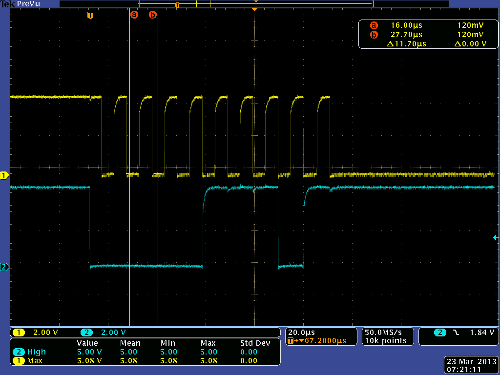
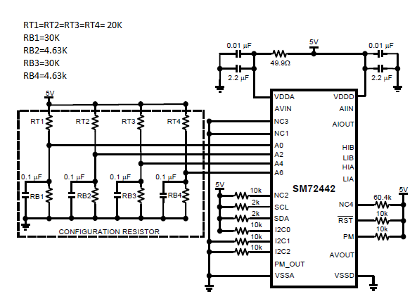
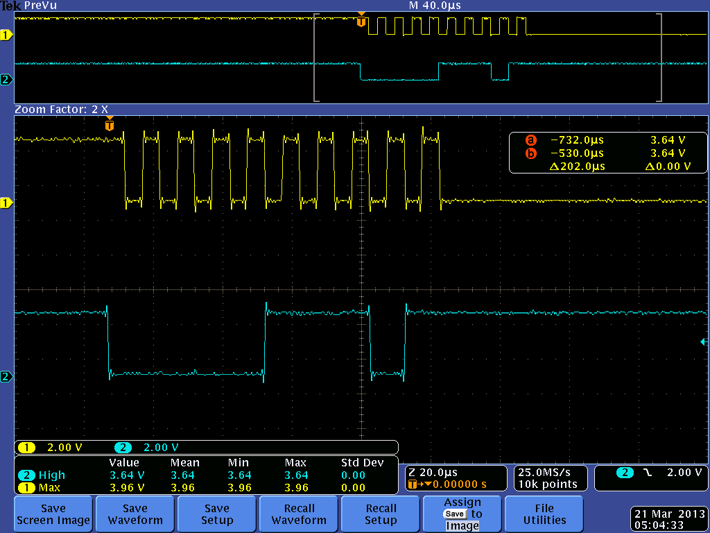
We are a senior design team working on the design of a MPPT charge controller. We are using the SM72442 and the MSP430G2553 launchPad to read out the values from the charge controller. When we run our i2c code we do not get an acknowledge bit from the SM72442. We are attaching the schematic of the configuration used only for communicating with the MSP430 via I2C.  In addition we have attached the screenshot from our oscilloscope displaying the clock (Yellow line) and data (Blue line) lines, but the SM72442 does not respond. we have reviewed the datasheet and carefully read page 13 for I2C communication. below is the link of the PDF for the SM72442.

http://www.ti.com/lit/ds/symlink/sm72442.pdf

Our address is: 0x07, and our I2C0=1; I2C1=1; I2C2=1

Please we do appreciate a prompt response, due that we are running out of time for the deadline of our project.

Thanks,

Andrea Solano


  • I'm having the same exact problem. I have read the datasheet like 20 times already, and can't figure out why the SM72442 doesn't respond.

  • Can you post your real schematic (not the cut'n'paste from the datasheet)?

    Also from the ds:

    Noise coupling into digital lines greater than 400 mVp-p (typical hysteresis) and undershoot less than 500 mV GND, may prevent successful I2C communication with SM72442. I2C no acknowledge is the most common symptom, causing unnecessary traffic on the bus although the I2C maximum frequency of communication is rather low (400 kHz max), care still needs to be taken to ensure proper termination within a system with multiple parts on the bus and long printed board traces. Additional resistance can be added in series with the SDA and SCL lines to further help filter noise and ringing. Minimize noise coupling by keeping digital races out of switching power supply areas as well as ensuring that digital lines containing high speed data communications cross at right angles to the SDA and SCL lines.

  • I'm operating at 100KHz, a little bit of noise but still no response. I have been able to communicate with other I2C devices effectively but not with the "SM72442".  Is there anyway you could post the schematic of the most basic setup or configuration to communicate with the SM72442?

    Thank You for your time.

  • I don't directly support that device, but i try to keep dialog active on the forum.  I'll see if I can find something out, but It will be Monday at the earliest.

  • Please and Thank You!

    The sooner the better.

  • John,

    Did you have time to take a look at our concern above? The SM72442 is still not responding to us. Please let me know if you are available. We have called TI as well, and they haven't respond to our request since last week.

    Thanks,

    Andrea

  • I'm making some inquiries to see if anynne can answer your questions.  Unfortunately, I do not know anything more about that device than what is in the datasheet.

  • Hi Andrea,

    It appears that the issue might be something else, perhaps with the way the IC is interfaced, or perhaps with the firmware used to talk to the device.  Have you tried toggling the ~RST line low for 300us before talking to the device?  It would help us to see the low-level I2C code you used to interface to this chip.  The way the I2C bus behaves is similar to the framing requirements of SMBUS.  If everything is setup correctly, you should be receiving an ACK.  By default the schematic in the datasheet that you copied has the 7-bit address as 0x01.

    Regards,

    Charles

  • Has anyone figured this out yet? I am having the same issue.

    Jesse